Sharp ARNC5J Service Manual - Page 3
] Installation - copiers
 |
View all Sharp ARNC5J manuals
Add to My Manuals
Save this manual to your list of manuals |
Page 3 highlights
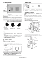
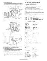
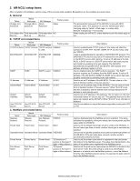
2. Jumper switches 2. Parts included 1 2 3 4 10BASE-T/ 100BASE-TX connector Jumper switch The jumper switch has No. 1 and No. 2 pins, and ON/OFF is switched by the jumper plug. When getting started, No. 1 pin is ON and the flash memory loader is started. When No. 2 is ON, the factory setting of the environmental variable is performed. Jumper witch ON OFF 1 Forcible loader mode Normal mode (When shipping) 2 Factory setup mode Normal mode (When shipping) Print server card: 1 CD-ROM: 1 Screws (silver) Spacers (unused): 2 M3 x 8: 2 Operation manual: 1 Installation manual: 1 3. Installation procedure The AR-NC5J installing procedures in the AR-235/275 series are described. In this case, no spacer is used in the packed items of the AR-NC5J. For the installing procedures of the AR-NC5J to another printer, refer to the printer's Service Manual or Installation Manual. Turn off the main switch of the copier and then remove the power plug of the copier from the outlet. 1) Remove the shielding plate. Remove five screws and remove the shielding plate. 1 2 Jumper plug Normal mode (When shipping) 1 2 Forcible loader mode 1 2 Factory setup NOTE: • When setting the jumper switch, be sure to turn off the power of the printer. • For normal use, be sure to set No. 1 and No. 2 to OFF (Normal mode). • The factory setup can be set by the utility or Telnet as well as the above jumper switch setup operations. Normally the utility or Telnet is used. Setting by the jumper switch is used only when the unit cannot make communication with the AR-NC5J. [5] INSTALLATION 1. Connection to a network To connect the AR-NC5J to a network, the following items are required. • For connection in the 100BASE-TX environment, a hub conforming to 100BASE-TX and a shield-type, twisted-pair cable (Category 5) are required. Screws 2) Cut and remove the cut-out portion from the left rear cabinet. Cut and remove the cut-out portion from the left rear cabinet using a tool such as nippers. (Be careful about the direction of the tool so that the cut surface is flat.) Cut-out portion 1234567 8 Hub Shield-type, twisted-pair cable 1) Check that the printer power is off, and connect the shield-type, twisted-pair cable to the 10/100BASE connector of the AR-NC5J. 2) Connect the other end of the cable to the hub. 3) Turn on the printer power, and check that the printer operates normally. AR-NC5J/NC5JG/NC5JW - 2
-
 1
1 -
 2
2 -
 3
3 -
 4
4 -
 5
5 -
 6
6 -
 7
7 -
 8
8 -
 9
9 -
10
-
11
-
12
 |
 |
