Sharp ARNC5J Service Manual - Page 4
Ar-nc5j Status Check - ar nc5j drivers
 |
View all Sharp ARNC5J manuals
Add to My Manuals
Save this manual to your list of manuals |
Page 4 highlights
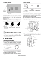
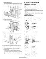
3) Attach the print server card. Align the connector positions, connect the print server card, and then secure the card to the option mounting plate in the main unit using supplied two silver screws (M3 x 8). Silver screws (M3 x 8) Print server card 4) Reattach the shielding plate. Reattach the shielding plate using five screws. [6] AR-NC5J STATUS CHECK 1. Printing the status page The AR-NC5J status is checked by printing the status page. A. Example of status page print There are roughly two ways of printing the status page. • Printing the status page is performed when starting the AR-NC5J. → Refer to the manual on the AR-NC5J setup. • Perform printing of the status page from the operation panel of the printer. → Some printers may not support it. Refer to the Operation Manual of the printer. ∗ The same information as the status page print-out can be obtained from the utility Web page. Screws 5) Connect the cable to the control PWB. Connect a LAN cable to the connector of the print server card. LAN cable Insert the power plug of the copier to the outlet and turn on the main switch. Then, carry out the following procedure. 6) Check for the print server card. Use the keys on the operation panel to print a configuration page. Check that the network interface card has been installed. 7) Check for printing. Peform setup of the environmental variables. (refer to [6]-2) (For installation of printer drivers on a computer and network settings (IP address input), see the supplied operation manual.) Execute printing to check to see if printing can be executed properly. AR-NC5J/NC5JG/NC5JW - 3
-
 1
1 -
 2
2 -
 3
3 -
 4
4 -
 5
5 -
 6
6 -
 7
7 -
 8
8 -
 9
9 -
 10
10 -
11
-
12
 |
 |
