Sharp GX20 Service Manual - Page 1
Sharp GX20 Manual
 |
View all Sharp GX20 manuals
Add to My Manuals
Save this manual to your list of manuals |
Page 1 highlights
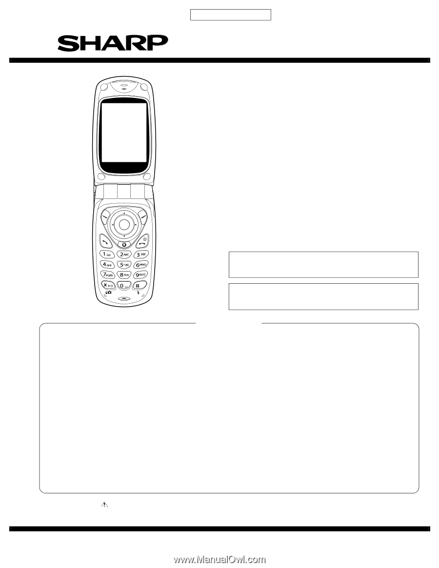
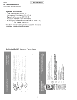
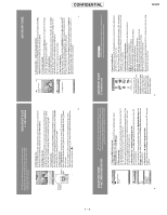
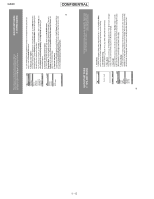
CONFIDENTIAL GX20 SERVICE MANUAL No. S9311TQGX20/B DIGITAL MOBILE PHONE MODEL GX20 (INTERNAL MODEL NAME: TQ-GX20E/G/R/T/S/H/EP/PP/W/B/D/A/Z/Q/L/F/C) E : For U.K. R : For Ireland S : For Spain EP: For U.K. (Prepaid) W : For Sweden D : For Greece Z : For New Zealand L : For Malta C : For Switzerland G : For Germany T : For Italy H : For Netherlands PP: For Portugal (Prepaid) B : For Hungary A : For Australia Q : For Egypt F : For France • In the interests of user-safety the set should be restored to its original condition and only parts identical to those specified should be used. • Caution Risk of explosion if battery is replaced by an incorrect type, dispose of used batteries according to the instruction. CONTENTS CHAPTER 1. GENERAL DESCRIPTION [1] Specifications 1-1 [2] Names of parts 1-2 [3] Operation manual 1-3 CHAPTER 2. ADJUSTMENTS [1] Adjustments SHARP Program Support Tool (SPST)........ 2-1 [2] SHARP RF Test tool manual 2-30 [3] Adjustment procedures after replacement of the parts 2-36 [4] Test points 2-39 [5] Troubleshooting 2-42 [6] Specification for function test 2-64 CHAPTER 4. DIAGRAMS [1] Block diagram 4-1 CHAPTER 5. SCHEMATIC DIAGRAM AND WIRING SIDE OF P.W.BOARD [1] Notes on schematic diagram 5-1 [2] Types of transistor and LED 5-1 [3] Waveforms of circuit 5-2 [4] Schematic diagram/ wiring side of P.W.Board 5-6 CHAPTER 6. OTHERS [1] Function table of IC 6-1 [2] Function table of Camera 6-27 CHAPTER 3. DISASSEMBLY AND REASSEMBLY [1] Servicing Concerns 3-1 [2] Disassembly and reassembly 3-5 Parts Guide Parts marked with " " are important for maintaining the safety of the set. Be sure to replace these parts with specified ones for maintaining the safety and performance of the set. SHARP CORPORATION This document has been published to be used for after sales service only. The contents are subject to change without notice.
-
 1
1 -
 2
2 -
 3
3 -
 4
4 -
 5
5 -
 6
6 -
 7
7 -
8
-
9
-
10
-
11
-
12
-
13
-
14
-
15
-
16
-
17
-
18
-
19
-
20
-
21
-
22
-
23
-
24
-
25
-
26
-
27
-
28
-
29
-
30
-
31
-
32
-
33
-
34
-
35
-
36
-
37
-
38
-
39
-
40
-
41
-
42
-
43
-
44
-
45
-
46
-
47
-
48
-
49
-
50
-
51
-
52
-
53
-
54
-
55
-
56
-
57
-
58
-
59
-
60
-
61
-
62
-
63
-
64
-
65
-
66
-
67
-
68
-
69
-
70
-
71
-
72
-
73
-
74
-
75
-
76
-
77
-
78
-
79
-
80
-
81
-
82
-
83
-
84
-
85
-
86
-
87
-
88
-
89
-
90
-
91
-
92
-
93
-
94
-
95
-
96
-
97
-
98
-
99
-
100
-
101
-
102
-
103
-
104
-
105
-
106
-
107
-
108
-
109
-
110
-
111
-
112
-
113
-
114
-
115
-
116
-
117
-
118
-
119
-
120
-
121
-
122
-
123
-
124
-
125
-
126
-
127
-
128
-
129
-
130
-
131
-
132
-
133
-
134
-
135
-
136
-
137
-
138
-
139
-
140
-
141
-
142
-
143
-
144
-
145
-
146
-
147
-
148
-
149
-
150
-
151
-
152
-
153
-
154
-
155
-
156
-
157
-
158
-
159
-
160
-
161
-
162
-
163
-
164
-
165
-
166
-
167
-
168
 |
 |