Sharp LC-15L1US LC-15L1U-S Operation Manual - Page 14
Antenna Connection Continued, Power Connection
 |
View all Sharp LC-15L1US manuals
Add to My Manuals
Save this manual to your list of manuals |
Page 14 highlights
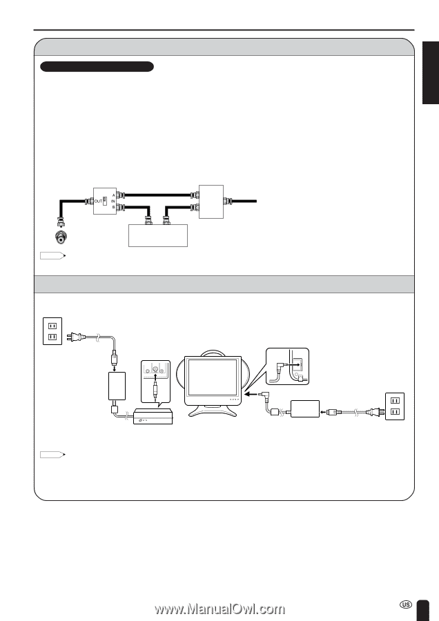
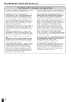
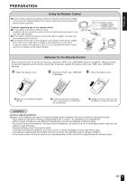
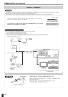
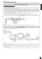
ENGLISH PREPARATION (Continued) Antenna Connection (Continued) CABLE TV (CATV) CONNECTION • A 75-ohm coaxial cable connector is built into the set for easy hookup. When connecting the 75-ohm coaxial cable to the set, screw the 75-ohm cable to the ANT. terminal. • Some cable TV companies offer "premium pay channels". Since the signals of these premium pay channels are scrambled, a cable TV converter/descrambler is generally provided to the subscriber by the cable TV company. This converter/ descrambler is necessary for normal viewing of the scrambled channels. (Set your TV to channel 3 or 4, typically one of these channels is used. If this is unknown, consult your cable TV company.) For more specific instructions on installing cable TV, consult your cable TV company. One possible method of utilizing the converter/descrambler provided by your cable TV company is explained below. Please note: An RF switch provided with two inputs (A and B) is required (not supplied). "A" position on the RF switch (not supplied): You can view all unscrambled channels by using the TV's channel keys. "B" position on the RF switch (not supplied): You can view the scrambled channels via the converter/descrambler by using the converter's channel keys. RF switch (not supplied) OUT IN Cable TV converter/ descrambler (not supplied) Two-set signal splitter (not supplied) Cable TV line Note: • Consult your SHARP Dealer or Service Center for the type of splitter, RF switch or combiner that might be required. Power Connection Connect to the DC input terminal of each product. AC wall outlet AC cord AC adapter IR OUT POWER FACTORY INPUT SETTING DC12V AC wall outlet Wireless Center TV main unit AC adapter AC cord Note: • Always turn the MAIN POWER button of the LCD TV set and the power button of the Wireless Center to OFF when connecting the AC adapters. • If there is a Sharp product close to the video controller, the product may malfunction during transmission of the video controller. • Unplug the AC adapters from the LCD TV set, Wireless Center unit and AC wall outlet when the LCD TV set is not to be used for a long period of time. 13
-
 1
1 -
2
-
3
-
4
-
5
-
6
-
7
-
8
-
 9
9 -
 10
10 -
 11
11 -
 12
12 -
 13
13 -
 14
14 -
 15
15 -
 16
16 -
 17
17 -
 18
18 -
 19
19 -
20
-
21
-
22
-
23
-
24
-
25
-
26
-
27
-
28
-
29
-
30
-
31
-
32
-
33
-
34
-
35
-
36
-
37
-
38
-
39
-
40
-
41
-
42
-
43
-
44
-
45
-
46
-
47
-
48
-
49
-
50
-
51
-
52
-
53
-
54
-
55
-
56
-
57
-
58
-
59
-
60
-
61
-
62
-
63
-
64
-
65
-
66
-
67
-
68
-
69
 |
 |