Sharp LC-15L1US LC-15L1U-S Operation Manual - Page 18
Wireless Center Part Names
 |
View all Sharp LC-15L1US manuals
Add to My Manuals
Save this manual to your list of manuals |
Page 18 highlights
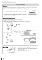
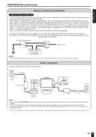
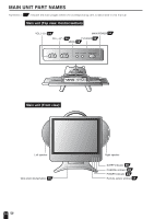
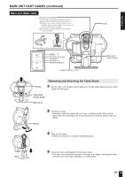
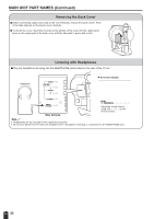
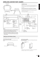
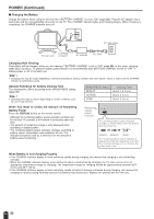
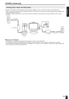
ENGLISH WIRELESS CENTER PART NAMES TV main unit Wireless Center Transmission POWER Indicator When the TV is turned off with the remote control, the Wireless Center is switched to standby (POWER indicator is lit red). (There may be a time lag of about 5 to 6 seconds.) Placing the Wireless Center Where You Want It We recommend placing the Wireless Center in an area where there are no obstructions to impede radio wave transmission/reception. (Do not place the Wireless Center in a box.) Front MAIN POWER POWER SIGNAL LEVEL MAIN POWER indicator POWER · Green: button Operation in progress (when power is on) · Red: Standby SIGNAL LEVEL indicator (Reception gain) · Green: Communication in progress · Red: Difficulty in transmission · Not lit: Not communicating Note: • The distance for which transmission is possible between the main unit and Wireless Center is about 15 metres. However, this distance may vary depending on the location or conditions under which the Wireless Center is used. • If the main unit gets close to the Wireless Center, there may be cases where noise appears on the screen. In this case, keep the main unit away from the Wireless Center until the noise decreases, or try to change the transmission channel setting (page 28). Rear Antenna input terminal VIDEO AV-IN1 AUDIO (L) AUDIO (R) AV-IN1 (S-VIDEO) IN ANT. OUT AV-IN3 AV-IN2 /OUT AV-IN1 MONITOR OUT AV-IN1 VIDEO AUDIO L AUDIO R MONITOR OUT S-VIDEO IR OUT POWER FACTORY INPUT SERVICE DC12V Antenna output terminal MONITOR OUT (S-VIDEO) MONITOR OUT VIDEO AUDIO (L) AUDIO (R) Factory adjustment terminal POWER INPUT DC 12V VIDEO AV-IN2 /OUT AUDIO (L) AUDIO (R) Video control terminal VIDEO AV-IN3 AUDIO (L) AUDIO (R) Setting up the Wireless Center • The Wireless Center can be placed horizontally or upright. • When placing horizontally: The side on which the rubber feet are attached is the bottom. • When placing upright: Fasten the stand to the bottom of the Wireless Center with the screws provided. Wireless Center stand Rubber foot Rubber foot * Failure to securely fasten the stand may cause the Wireless Center to tip over during use. 17
-
 1
1 -
2
-
3
-
4
-
5
-
6
-
7
-
8
-
9
-
10
-
11
-
12
-
 13
13 -
 14
14 -
 15
15 -
 16
16 -
 17
17 -
 18
18 -
 19
19 -
 20
20 -
 21
21 -
 22
22 -
 23
23 -
24
-
25
-
26
-
27
-
28
-
29
-
30
-
31
-
32
-
33
-
34
-
35
-
36
-
37
-
38
-
39
-
40
-
41
-
42
-
43
-
44
-
45
-
46
-
47
-
48
-
49
-
50
-
51
-
52
-
53
-
54
-
55
-
56
-
57
-
58
-
59
-
60
-
61
-
62
-
63
-
64
-
65
-
66
-
67
-
68
-
69
 |
 |
