Sharp LC-15L1US LC-15L1U-S Operation Manual - Page 61
How to Use Video 1 Output
 |
View all Sharp LC-15L1US manuals
Add to My Manuals
Save this manual to your list of manuals |
Page 61 highlights
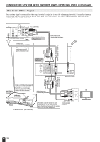
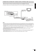
CONNECTION SYSTEM WITH VARIOUS WAYS OF BEING USED (Continued) How to Use Video 1 Output Since a video signal received at the video input terminal is output as is from the video output terminal, it is possible to enjoy pictures and sounds from an external device (such as a VCR) connected to the video 1 input on another television while watching television on the main unit. AUDIO COAXIAL DIGITAL S-VIDEO R OPTICAL OUT R (INRedA)NT R AUDIO (WAhUDiIOte) L L TV VIDEO (YeVlIlDoEOw) To Audio/Video output terminal L To S-VIDEO output terminal Rear Connect to the terminal of the same color. S-video cord (commercially available) When connecting to equipment having an S-video terminal. Audio/Video cord (commercially available) To Video control terminal To AV-IN1 (S-VIDEO) terminal (Red) (White) (Yellow) To AV-IN1 (AV) terminal Connect to the terminal of the same color. IN ANT. AV-IN3 AV-IN2 /OUT AV-IN1 MONITOR OUT AV-IN1 VIDEO AUDIO L OUT AUDIO R MONITOR OUT S-VIDEO IR OUT POWER FACTORY INPUT SERVICE DC12V Wireless Center To MONITOR OUT (S-VIDEO) terminal (Red) (White) (Yellow) To MONITOR OUT (AV) terminal Installation example Video controller (supplied) (The video controller should be fixed with the accessory tape once the place where it is to be installed has been decided.) VCR etc. Audio/Video cord (commercially available) (Yellow) VIDEO (White) L (Red) AUDIO R TV Front Infrared receiver (an example) S-VIDEO The video controller is fixed so that the transmitter of the video controller faces the infrared receiver of the remote control for the video equipment. S-video cord (commercially available) 60
-
 1
1 -
2
-
3
-
4
-
5
-
6
-
7
-
8
-
9
-
10
-
11
-
12
-
13
-
14
-
15
-
16
-
17
-
18
-
19
-
20
-
21
-
22
-
23
-
24
-
25
-
26
-
27
-
28
-
29
-
30
-
31
-
32
-
33
-
34
-
35
-
36
-
37
-
38
-
39
-
40
-
41
-
42
-
43
-
44
-
45
-
46
-
47
-
48
-
49
-
50
-
51
-
52
-
53
-
54
-
55
-
 56
56 -
 57
57 -
 58
58 -
 59
59 -
 60
60 -
 61
61 -
 62
62 -
 63
63 -
 64
64 -
 65
65 -
 66
66 -
67
-
68
-
69
 |
 |
