Sharp T19D1-H Operation Manual - Page 25
This monitor supports the VESA DDC Display
 |
UPC - 074000047792
View all Sharp T19D1-H manuals
Add to My Manuals
Save this manual to your list of manuals |
Page 25 highlights
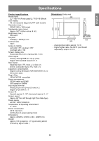
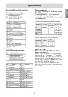
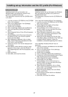
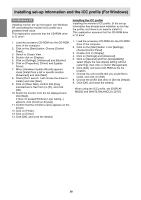
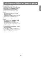
English Español Italiano Français Deutsch English Specifications The analog RGB input connector pin (Mini D-sub connector with 15 pins) No. Function 1 Red video signal input 2 Green video signal input 3 Blue video signal input 4 GND 5 GND 6 For red video signal GND 7 For green video signal GND 8 For blue video signal GND 9 +5V 10 GND 11 N.C. 12 DDC data 13 For Hsync signal input 14 For Vsync signal input 15 DDC clock The DVI-D input connector pin (DVI-D connector with 24 pins) No. Function No. Function 1 TMDS data 2- 13 N.C. 2 TMDS data 2+ 14 +5V 3 TMDS data 2/4 shield 15 GND 4 N.C. 16 Hot plug detection 5 N.C. 17 TMDS data 0- 6 DDC clock 18 TMDS data 0+ 7 DDC data 19 TMDS data 0/5 shield 8 N.C. 20 N.C. 9 TMDS data 1- 21 N.C. 10 TMDS data 1+ 22 TMDS clock shield 11 TMDS data 1/3 shield 23 TMDS clock + 12 N.C. 24 TMDS clock - Power management The monitor is based on the VESA DPMS and the DVI DMPM standards. To activate the monitor's Power Management function, both the video card and the computer must conform to the VESA DPMS standard and the DVI DMPM standard. DPMS: Display Power Management Signaling Power DPMS mode Screen consumption H-sync V-sync ON Display on 43 W Yes Yes STANDBY No Yes SUSPEND Display off OFF 2.8 W Yes No No No DMPM: Digital Monitor Power Management DMPM mode Screen Power consumption ON Display on 43 W OFF Display off 2.8 W DDC (Plug & Play) This monitor supports the VESA DDC (Display Data Channel) standard. DDC is a signal standard for carrying out Plug & Play functions on the monitor or PC. It transfers information such as degree of resolution between the monitor and PC. You can use this function if your PC is DDC compliant and if it is set so that it can detect the Plug & Play monitor. There are many varieties of DDC due to the differences between systems. This monitor works with DDC2B. 25
-
 1
1 -
2
-
3
-
4
-
5
-
6
-
7
-
8
-
9
-
10
-
11
-
12
-
13
-
14
-
15
-
16
-
17
-
18
-
19
-
 20
20 -
 21
21 -
 22
22 -
 23
23 -
 24
24 -
 25
25 -
 26
26 -
 27
27 -
 28
28 -
 29
29 -
 30
30 -
31
-
32
-
33
-
34
-
35
-
36
-
37
-
38
-
39
-
40
-
41
-
42
-
43
-
44
-
45
-
46
-
47
-
48
-
49
-
50
-
51
-
52
-
53
-
54
-
55
-
56
-
57
-
58
-
59
-
60
-
61
-
62
-
63
-
64
-
65
-
66
-
67
-
68
-
69
-
70
-
71
-
72
-
73
-
74
-
75
-
76
-
77
-
78
-
79
-
80
-
81
-
82
-
83
-
84
-
85
-
86
-
87
-
88
-
89
-
90
-
91
-
92
-
93
-
94
-
95
-
96
-
97
-
98
-
99
-
100
-
101
-
102
-
103
-
104
-
105
-
106
-
107
-
108
-
109
-
110
-
111
-
112
-
113
-
114
-
115
-
116
-
117
-
118
-
119
-
120
-
121
-
122
-
123
-
124
-
125
-
126
-
127
-
128
-
129
-
130
-
131
-
132
 |
 |
