Sharp VL-A111UL Service Manual
Sharp VL-A111UL Manual
 |
View all Sharp VL-A111UL manuals
Add to My Manuals
Save this manual to your list of manuals |
Sharp VL-A111UL manual content summary:
- Sharp VL-A111UL | Service Manual - Page 1
SERVICE MANUAL VL-A111U/AH131U VL-AH151U/AH161U SERVICE MANUAL SY1VL-A111U// LIQUID CRYSTAL CAMCORDER Hi 8 NTSC MODELS VL-A111U VL-AH131U VL-AH151U VL .PACKING OF THE SET ...120 SHARP CORPORATION This document has been published to be used for after sales service only. 1The contents are subject - Sharp VL-A111UL | Service Manual - Page 2
VL-A111U/AH131U VL-AH151U/AH161U 1. IMPORTANT SERVICE NOTES BEFORE RETURNING THE VIDEO CAMERA RECORDER EXPOSED METAL PARTS 0.15 µF TEST PROBE CONNECT TO KNOWN EARTH GROUND 1. NOTES DE SERVICE IMPORTANTES AVANT DE RENDRE LE MAGNETOSCOPE Avant de rendre le magnétoscope à l'utilisateur, effectuer - Sharp VL-A111UL | Service Manual - Page 3
VL-A111U/AH131U VL-AH151U/AH161U WARNING :TO REDUCE THE RISK OF FIRE OR ELECTRIC SHOCK, DO NOT EXPOSE THIS APPLIANCE TO WET LOCATIONS. CAUTION RISK OF ELECTRIC SHOCK DO NOT OPEN CAUTION: TO REDUCE THE RISK OF ELECTRIC SHOCK. DO NOT REMOVE COVER. NO USER·SERVICEABLE PARTS INSIDE. REFER SERVICING TO - Sharp VL-A111UL | Service Manual - Page 4
VL-A111U/AH131U VL-AH151U/AH161U CAUTION BEFORE BATTERY DESTROY NICKEL-CADMIUM BATTERY The following program is available in the United States. Please consult local environmental authorities concerning the availability of this or other programs in your area. The RBRCTM Seal SHARP participates in - Sharp VL-A111UL | Service Manual - Page 5
battery pack) DC 7.0V (with AC adapter) Power Consumption: VL-A111U/AH131U/AH151U : 5.1W VL-AH161U : 5.2W (during camera recording in full auto mode with to change without notice. SERVICE INFORMATION (For the U.S.) For the location of the nearest Sharp Authorized Service, or to obtain product - Sharp VL-A111UL | Service Manual - Page 6
VL-A111U/AH131U VL-AH151U/AH161U 3. PART NAMES AND FUNCTION For details on the use of each control. 6 Front view Zoom lens Microphone Terminal cover AUDIO/VIDEO jack Speaker - Sharp VL-A111UL | Service Manual - Page 7
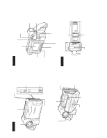
Note: Before removing the cabinet, turn off the power supply, and ascertain that the battery has been removed. (b) VL-A111U/AH131U VL-AH151U/AH161U (b) Pull out Connector (a) (d) (1) (a) Camera front cabinet 1. Remove one screw ((d)XiPSF20P04000), one screw ((b)LXHZ0018TAFF), two screws - Sharp VL-A111UL | Service Manual - Page 8
VL-A111U/AH131U VL-AH151U/AH161U 4-2. DISASSEMBLY OF THE VCR MAIN BODY Area A (k) (1) Remove one screw ((k)LX-HZ0063TAFN). VCR lid - Sharp VL-A111UL | Service Manual - Page 9
Caution for installation of the VCR lid VL-A111U/AH131U VL-AH151U/AH161U Microphone connector VCR lid Area B (1) Disconnect the microphone connector. Microphone connector Microphone wire spacer Microphone connector When installing the VCR - Sharp VL-A111UL | Service Manual - Page 10
VL-A111U/AH131U VL-AH151U/AH161U (b) LCD unit Connector Lithium PWB Main PWB Connector Inverter transformer (3) Remove two screws ((b)LX-HZ0018TAFF) and two connec- (1) - Sharp VL-A111UL | Service Manual - Page 11
compartment lid are securely engaged as shown in the view above. VL-A111U/AH131U VL-AH151U/AH161U (2) Claw (A) Lugs (3) (1) Claw (A) Reflection sheet Light guide plate Diffusion sheet Prism sheet Lugs Claw (B) Disengage the claw, and remove the LCD panel - Sharp VL-A111UL | Service Manual - Page 12
VL-A111U/AH131U VL-AH151U/AH161U 4-3. REPLACEMENT OF CCD SENSOR 4-3-1. BEFORE REPLACEMENT 1) soldering with a soldering iron which is grounded to prevent static electricity. 1 7 Index Mark JAPAN SHARP RJ2411 YYWWXXX 14 8 CCD bottom view 4-3-2. REMOVAL OF CCD 1) Unsolder the CCD sensor leads - Sharp VL-A111UL | Service Manual - Page 13
VL-A111U/AH131U VL-AH151U/AH161U 5. MECHANISM ADJUSTMENT 5-1. MECHANISM CHECKING/ADJUSTING JIGS, TOOLS AND height and guide height and Si checking of reel disk height roller height 1. Tu guide height adjusting driver 2. 9EQDRiVER-V712 3. BL 2 1.8 Edge 4 thickness 0.5 1. Guide roller height - Sharp VL-A111UL | Service Manual - Page 14
VL-A111U/AH131U VL-AH151U/AH161U 5-2. ITEMS AND TIMINGS OF INSPECTION AND MAINTENANCE The the parts is required. (3) Oils a) Be sure to use the specified oils (different viscosity may cause troubles). b) For the bearings, be sure to use oil that is free form dust and other foreign substances. - Sharp VL-A111UL | Service Manual - Page 15
VL-A111U/AH131U VL-AH151U/AH161U 5-3. MECHANISM CHECKS AND ADJUSTMENTS The description given below relates to the general field services, but does not relate to the adjustment and replacement that require high level equipment, jigs, and technical skills. In order to maintain the initial - Sharp VL-A111UL | Service Manual - Page 16
VL-A111U/AH131U VL-AH151U/AH161U 5-3-4. Checking and adjusting the tension pole position (1) Check When it begins to wind the P6-120 tape check whether the tension pole is - Sharp VL-A111UL | Service Manual - Page 17
VL-A111U/AH131U VL-AH151U/AH161U 5-4. ADJUSTMENT OF MECHANISM TAPE RUNNING SYSTEM 5-4-1. Preparation for adjustment (1) Clean the tape running areas (guide poles, rollers, drum, ,, Capstan shaft, Pinch roller) (Figure 1) ,, (2) Connect the oscilloscope to the following TPs. Sup tilted pole Tu GR - Sharp VL-A111UL | Service Manual - Page 18
VL-A111U/AH131U VL-AH151U/AH161U 5-4-4. Adjusting the Tu guide After replacement of Tu guide preset and adjust the height. (1) Tu guide height presetting ( flange of Sup GR, upper flange of Tu GR, and upper/lower flange of Tu guide. Si roller Sup GR Tu GR Drum 2 In case of V/S F and R ascertain - Sharp VL-A111UL | Service Manual - Page 19
VL-A111U/AH131U VL-AH151U/AH161U 5-5. MECHANISM ASSEMBLING AND PARTS REPLACEMENT (DISASSEMBLING AND ASSEMBLING) Below is given an explanation of assembling of mechanism and its parts replacement. The removal of cabinet and the PWB is explained in the relevant service manual. Notes 1 After - Sharp VL-A111UL | Service Manual - Page 20
VL-A111U/AH131U VL (2) Remove the four screws 2 and take out the down guide 3. (3) Slide the two link support shafts c and the two roller shafts d to the round 6 referring to the Service Manual (so as to actuate the mechanism). Cap (2) Put the cap on the light guide. (3) Press the cassette - Sharp VL-A111UL | Service Manual - Page 21
Sub-cam (2) Main cam (4) Mode switch Lo relay gear VL-A111U/AH131U VL-AH151U/AH161U Phase matching mark (Round hole) Mode switch Phase washers. (3) Install the segment gear, T arm guide, the M-function lever and the eject lever. a T arm guide Segment gear M-function lever Move claw to rear - Sharp VL-A111UL | Service Manual - Page 22
-A111U/AH131U VL-AH151U/AH161U (4) Install the loading block assembly and the capstan motor. (5) Install the drive gear. At this time, pay attention to the direction of gear. (The small gear must be located in the chassis side.) a A a a Loading motor Capstan motor a (7) Install the guide - Sharp VL-A111UL | Service Manual - Page 23
. (10) Install the Si roller. B (11) Install the slide chassis. T arm guide VL-A111U/AH131U VL-AH151U/AH161U Tape guide A Drum assembly A A Slide this part towards the T arm. Place the slide chassis on the guide rail. A B Si roller Roller spring B Main cam pin B Insert the main cam - Sharp VL-A111UL | Service Manual - Page 24
VL-A111U/AH131U VL-AH151U/AH161U parts have all been perfectly adjusted). In case a trouble or troubles are found in the electric circuitry, be sure to pinpoint smallsized, surface-mounted type. For replacing part(s) as after-sales, service, work with a soldering iron as speedily as possible. The - Sharp VL-A111UL | Service Manual - Page 25
VL-A111U/AH131U VL-AH151U/AH161U 6-3-4. Setting value Table 1) When IC705 is replaced Model Destination Specification Menu 1 Menu 2 VTR ADJ ADD. 01 09 02 0A 03 0B 04 0C 05 0D A111U FF FF Table 3) When IC002 is replaced CAM DATA ADJ A111U AH151U ADD. AH131U AH161U 1 0A9 - 01 2 0AA - - Sharp VL-A111UL | Service Manual - Page 26
VL-A111U/AH131U VL-AH151U/AH161U 6-4. TEST mode TEST No. Title 1 Sensor Off 2 Mecha Adjustment mode 3 Shut Off Adjustment 4 Error Display 5 PASS mode 6 Cam Adjustment mode 7 VCR Adjustment mode 8 - Sharp VL-A111UL | Service Manual - Page 27
VL-A111U/AH131U VL-AH151U/AH161U 1 2 3 4 5 1. Extension Cable Inverter~VCR (7pin) 2. QCNW- 1. Connector fitting and withdrawing tweezers withdrawing extractor 2. 9EQPiNSET06GE 3. BR 1. Service remote control 2. RRMCG0033TASA 3. BT · Alignment Tape JiGWR5-5NSP (NTSC) - Sharp VL-A111UL | Service Manual - Page 28
VL-A111U/AH131U VL-AH151U/AH161U 6-6-3. VCR circuit adjustment * Before adjusting the VCR circuit, make sure that the fixed value in 6-3-2 is written in E2PROM. · Test points on the - Sharp VL-A111UL | Service Manual - Page 29
(Sig) TL9414 (Gnd) Adjustment standard ME 115±5mVP-P MP 105±5mVP-P ME 135±5mVP-P MP 120±5mVP-P Measuring instrument Oscilloscope · Nor8model (VL-A111U) VTR ADJ Mode REC C current VCR adjustment (Nor 8) STOP Address 46 Measuring point TL9413 (Sig) TL9414 (Gnd) Adjustment standard MP 120 - Sharp VL-A111UL | Service Manual - Page 30
VL-A111U/AH131U VL-AH151U/AH161U 6-6-3-4. Adjustment of audio circuit 1. Adjustment of filter f0 Measuring instrument Oscilloscope Mode Input signal (tape) PB JiGWR5-5NSP Measuring terminal TL605/AUDIO.OUT - Sharp VL-A111UL | Service Manual - Page 31
03E VCR 1) Connect TL3803 to GND. 2) Connect the frequency counter to TL3802, and adjust the frequency. 15.734kHz ± 100Hz ------- VL-A111U/AH131U VL-AH151U/AH161U 6. H-position adjustment Measuring point TL3802 Address(VTR ADJ) 03B Mode VCR Adjusting method 1) Connect the oscilloscope to - Sharp VL-A111UL | Service Manual - Page 32
VL-A111U/AH131U VL-AH151U/AH161U 6-7. CAM section adjustment 6-7-1. CAM section adjustment jigs (1) Object, measuring instrument and jigs necessary for camera section servicing • Gray scale chart • Vectorscope • Extension cable • Oscilloscope • Video output cable • Color bar chart • Color - Sharp VL-A111UL | Service Manual - Page 33
6-7-3. CAM circuit adjustment * Before adjusting the CAM circuit, make sure that the fixed value in 6-3-3 is written in E2PROM. VL-A111U/AH131U VL-AH151U/AH161U 6-7-3-1. Supply voltage check Check that the voltages at the following TL are within the specified range (refer to the supply voltage - Sharp VL-A111UL | Service Manual - Page 34
VL-A111U/AH131U VL-AH151U/AH161U 6-7-3-6. Black balance, AF noise level adjustment Mode Measuring instrument Subject Measuring point Adjustment address Adjustment reference CAM ADJ - Not specified - 71 01 1) Write - Sharp VL-A111UL | Service Manual - Page 35
SHOOTING 6-8-1. Classification of troubles No operation at all No tape ejection No LCD light-up No picture in EE mode No picture playback No video recording Streaking at self-recording/playback Black streaking VL-A111U/AH131U VL-AH151U/AH161U ûYES Check the Power circuit and system control circuit - Sharp VL-A111UL | Service Manual - Page 36
û VL-A111U/AH131U VL-AH151U/AH161U 6-8-2. Troubleshooting for the camera section No picture No color ûYES Check the lens drive circuit (IC551) and main signal line. ûYES Check IC401 (DSP), and its - Sharp VL-A111UL | Service Manual - Page 37
NONREGE IC900 POWER (CAMERA) Power Control IC IC701 3.0V Reg POWER (SYS 3.0V) POWER (AT 3.0V) IC706 I CHIP µ-COM SYSTEM CONTROL VL-A111U/AH131U VL-AH151U/AH161U KEY IC2 E2PROM LENS IC102 D/A CDS IC101 DSP IC401 LCD CAM Y/C ATF IC2701 D/A SERIAL BUS POWER (SIGNAL) AUDIO IC601 IC301 - Sharp VL-A111UL | Service Manual - Page 38
VL-A111U/AH131U VL-AH151U/AH161U 7-2. SIGNAL PROCESS BLOCK DIAGRAM 38 32 LENS IC1 Q1 CCD 4 SENSOR CCD_OUT 6, 7 10 13 ACC_AMP 25, 26 CDS_AGC CDS AGC / ACC IC101 40, - Sharp VL-A111UL | Service Manual - Page 39
HEAD AMP 17 32 30 REC-Y Q407 BUFFER Q8451 FILTER Q8401/Q8402 FILTER Q8452 MIX AMP EQ Q8404 REC-C REC_AFM FROM AUDIO 7-2-1. RECORDING SIGNAL FLOW (VL-A111U/AH131U) VL-A111U/AH131U VL-AH151U/AH161U - Sharp VL-A111UL | Service Manual - Page 40
-AH151U/AH161U 7-2-2. PLAY BACK SIGNAL FLOW (VL-A111U/AH131U) 40 32 LENS IC1 Q1 CCD 4 SENSOR CCD_OUT 6, 7 10 13 ACC_AMP 25, 26 CDS_AGC CDS AGC / ACC IC101 40, 42 IC12 TIMING GENERATOR IC11 3, 5, - Sharp VL-A111UL | Service Manual - Page 41
HEAD AMP 17 32 30 REC-Y Q407 BUFFER Q8451 FILTER Q8401/Q8402 FILTER Q8452 MIX AMP EQ Q8404 REC-C REC_AFM FROM AUDIO 7-2-3. RECORDING SIGNAL FLOW (VL-AH151U/AH161U) VL-A111U/AH131U VL-AH151U/AH161U - Sharp VL-A111UL | Service Manual - Page 42
VL-A111U/AH131U VL-AH151U/AH161U 7-2-4. PLAY BACK SIGNAL FLOW (VL-AH151U/AH161U) 42 32 LENS IC1 Q1 CCD 4 SENSOR CCD_OUT 6, 7 10 13 ACC_AMP 25, 26 CDS_AGC CDS AGC / ACC IC101 40, 42 IC12 TIMING GENERATOR - Sharp VL-A111UL | Service Manual - Page 43
4.9V 3.3V CAM HEAD 3.1V MECHA 5V 4.9V -8V 15V SYS 3.1V 4.9V NONREG SYSDAC P-CON4.9V D/A4.9V D/A3.3V 7-3. POWER SYSTEM BLOCK DIAGRAM VL-A111U/AH131U VL-AH151U/AH161U - Sharp VL-A111UL | Service Manual - Page 44
VL-A111U/AH131U VL-AH151U/AH161U 7-4. MAIN BATTERY CIRCUIT SECTION BLOCK DIAGRAM 44 DC JACK input Q2901 Voltage detective circuit VDC - Sharp VL-A111UL | Service Manual - Page 45
7-5. LENS DRIVE BLOCK DIAGRAM VL-A111U/AH131U VL-AH151U/AH161U ZOOM LENS IC1 CCD SENSOR MASTER LENS MASTER LENS POSI IC101 CDS AGC IC151 A/D IC401 42 DSP 49 41 DATA 48 IC706 SYSTEM - Sharp VL-A111UL | Service Manual - Page 46
VL-A111U/AH131U VL-AH151U/AH161U 8. SCHEMATIC DIAGRAMS 8-1. OVERALL SCHEMATIC DIAGRAM J I H (VL-A111U/AH131U/AH151U) (VL-AH161U) (VL-A111U/AH131U/AH151U) (VL-AH161U) RUNTKA010WJZZ G F E D C B A 1 2 3 4 5 6 7 8 9 10 11 12 13 14 15 16 17 18 19 20 46~47 - Sharp VL-A111UL | Service Manual - Page 47
VL-A111U/AH131U VL-AH151U/AH161U 8-2. A/D_CONVERTER SCHEMATIC DIAGRAM J I H G F E D C B A 1 2 3 4 5 6 7 8 9 10 11 12 13 14 15 16 17 18 19 20 48~49 - Sharp VL-A111UL | Service Manual - Page 48
VL-A111U/AH131U VL-AH151U/AH161U 8-3. ZOOM SCHEMATIC DIAGRAM(VL-AH151U/AH161U only) J I H G F E D C B A 1 2 3 4 5 6 7 8 9 10 11 12 13 14 15 16 17 18 19 20 50~51 - Sharp VL-A111UL | Service Manual - Page 49
VL-A111U/AH131U VL-AH151U/AH161U 8-4. DSP SCHEMATIC DIAGRAM(VL-A111U/AH131U) J I H G F E D C B A 1 2 3 4 5 6 7 8 9 10 11 12 13 14 15 16 17 18 19 20 52~53 - Sharp VL-A111UL | Service Manual - Page 50
VL-A111U/AH131U VL-AH151U/AH161U 8-4. DSP SCHEMATIC DIAGRAM(VL-AH151U/AH161U) J I H G F E D C B A 1 2 3 4 5 6 7 8 9 10 11 12 13 14 15 16 17 18 19 20 54~55 - Sharp VL-A111UL | Service Manual - Page 51
VL-A111U/AH131U VL-AH151U/AH161U 8-5. AUDIO SCHEMATIC DIAGRAM J I H G F E D C B A 1 2 3 4 5 6 7 8 9 10 11 12 13 14 15 16 17 18 19 20 56~57 - Sharp VL-A111UL | Service Manual - Page 52
VL-A111U/AH131U VL-AH151U/AH161U 8-6. SYSTEM CONTROL SCHEMATIC DIAGRAM(VL-A111U/AH131U) J I H G F E D C B A 1 2 3 4 5 6 7 8 9 10 11 12 13 14 15 16 17 18 19 20 58~59 - Sharp VL-A111UL | Service Manual - Page 53
VL-A111U/AH131U VL-AH151U/AH161U 8-6. SYSTEM CONTROL SCHEMATIC DIAGRAM(VL-AH151U/AH161U) J I H G F E D C B A 1 2 3 4 5 6 7 8 9 10 11 12 13 14 15 16 17 18 19 20 60~61 - Sharp VL-A111UL | Service Manual - Page 54
VL-A111U/AH131U VL-AH151U/AH161U 8-7. LCD INTERFACE SCHEMATIC DIAGRAM J I H G F E D C B A 1 2 3 4 5 6 7 8 9 10 11 12 13 14 15 16 17 18 19 20 62~63 - Sharp VL-A111UL | Service Manual - Page 55
VL-A111U/AH131U VL-AH151U/AH161U 8-8. POWER CONTROL SCHEMATIC DIAGRAM J å AND SHADED COMPONENTS=SAFETY RELATED PARTS I H G F å E D C B A 1 2 3 4 5 6 7 8 9 10 11 12 13 14 15 16 17 18 19 20 64~65 - Sharp VL-A111UL | Service Manual - Page 56
VL-A111U/AH131U VL-AH151U/AH161U 8-9. VIDEO OUT SCHEMATIC DIAGRAM J I H G F E D C B A 1 2 3 4 5 6 7 8 9 10 11 12 13 14 15 16 17 18 19 20 66~67 - Sharp VL-A111UL | Service Manual - Page 57
VL-A111U/AH131U VL-AH151U/AH161U 8-10. D/A CONVERTER SCHEMATIC DIAGRAM J I H G F E D C B A 1 2 3 4 5 6 7 8 9 10 11 12 13 14 15 16 17 18 19 20 68~69 - Sharp VL-A111UL | Service Manual - Page 58
VL-A111U/AH131U VL-AH151U/AH161U 8-11. CHARGE SCHEMATIC DIAGRAM J å AND SHADED COMPONENTS=SAFETY RELATED PARTS I å å H G F å E D C B A 1 2 3 4 5 6 7 8 9 10 11 12 13 14 15 16 17 18 19 20 70~71 - Sharp VL-A111UL | Service Manual - Page 59
VL-A111U/AH131U VL-AH151U/AH161U 8-12. LCD CONTROLLER SCHEMATIC DIAGRAM(VL-A111U/AH131U/AH151U) J I H G F E D C B A 1 2 3 4 5 6 7 8 9 10 11 12 13 14 15 16 17 18 19 20 72~73 - Sharp VL-A111UL | Service Manual - Page 60
VL-A111U/AH131U VL-AH151U/AH161U 8-12. LCD CONTROLLER SCHEMATIC DIAGRAM(VL-AH161U) J I H G F E D C B A 1 2 3 4 5 6 7 8 9 10 11 12 13 14 15 16 17 18 19 20 74~75 - Sharp VL-A111UL | Service Manual - Page 61
VL-A111U/AH131U VL-AH151U/AH161U 8-13. RF SCHEMATIC DIAGRAM(VL-A111U) J I H G F E D C B A 1 2 3 4 5 6 7 8 9 10 11 12 13 14 15 16 17 18 19 20 76~77 - Sharp VL-A111UL | Service Manual - Page 62
VL-A111U/AH131U VL-AH151U/AH161U 8-13. RF SCHEMATIC DIAGRAM(VL-AH131U/AH151U/AH161U) J I H G F E D C B A 1 2 3 4 5 6 7 8 9 10 11 12 13 14 15 16 17 18 19 20 78~79 - Sharp VL-A111UL | Service Manual - Page 63
VL-A111U/AH131U VL-AH151U/AH161U 8-14. TG SCHEMATIC DIAGRAM J I H G F E D C B A 1 2 3 4 5 6 7 8 9 10 11 12 13 14 15 16 17 18 19 20 80~81 - Sharp VL-A111UL | Service Manual - Page 64
VL-A111U/AH131U VL-AH151U/AH161U 8-15. CDS AGC/ACC SCHEMATIC DIAGRAM J I H G F E D C B A 1 2 3 4 5 6 7 8 9 10 11 12 13 14 15 16 17 18 19 20 82~83 - Sharp VL-A111UL | Service Manual - Page 65
VL-A111U/AH131U VL-AH151U/AH161U 8-16. LENS DRIVER SCHEMATIC DIAGRAM J I H G F E D C B A 1 2 3 4 5 6 7 8 9 10 11 12 13 14 15 16 17 18 19 20 84~85 - Sharp VL-A111UL | Service Manual - Page 66
VL-A111U/AH131U VL-AH151U/AH161U 8-17. HEAD AMP SCHEMATIC DIAGRAM J I H G F E D C B A 1 2 3 4 5 6 7 8 9 10 11 12 13 14 15 16 17 18 19 20 86~87 - Sharp VL-A111UL | Service Manual - Page 67
VL-A111U/AH131U VL-AH151U/AH161U 8-18. MOTOR DRIVER SCHEMATIC DIAGRAM J I H G F E D C B A 1 2 3 4 5 6 7 8 9 10 11 12 13 14 15 16 17 18 19 20 88~89 - Sharp VL-A111UL | Service Manual - Page 68
VL-A111U/AH131U VL-AH151U/AH161U 8-19. CCD SCHEMATIC DIAGRAM J I H G F E D C B A 1 2 3 4 5 6 7 8 9 10 11 12 13 14 15 16 17 18 19 20 90~91 - Sharp VL-A111UL | Service Manual - Page 69
VL-A111U/AH131U VL-AH151U/AH161U 9. PRINTED WIRING BOARD ASSEMBLIES VCR PWB Component Side SIDE A J I Q903 R904 Z2 R2915 R2911 Q2907 R2944 C2906 R2921 IC2901 C942 R2902 R2901 Q2910 - Sharp VL-A111UL | Service Manual - Page 70
VCR PWB Wiring Side SIDE A J VL-A111U/AH131U VL-AH151U/AH161U I H G F E D C B A 1 2 3 4 5 6 7 8 9 10 93 - Sharp VL-A111UL | Service Manual - Page 71
VL-A111U/AH131U VL-AH151U/AH161U VCR PWB Component Side SIDE B J I R2934 R2908 R749 C733 R929 R2913 P601 CN3601 TL3603 TL3604 TL3601 TL360T7L3602 TL606 TL360T9L3608 TL609TL610 H TL36T1L236T1L13610 TL60T8L604 C601 - Sharp VL-A111UL | Service Manual - Page 72
VCR PWB Wiring Side SIDE B J VL-A111U/AH131U VL-AH151U/AH161U I H G F E D C B A 1 2 3 4 5 6 7 8 9 10 95 - Sharp VL-A111UL | Service Manual - Page 73
VL-A111U/AH131U VL-AH151U/AH161U CAMERA PWB Component Side SIDE A J P101 Z1 I SC101 TL107 H TL103 TL109 TL108 TL106 TL105 TL104 R17 R18 R21 R11 R13 R12 TL26 TL19 - Sharp VL-A111UL | Service Manual - Page 74
CAMERA PWB Wiring Side SIDE A J VL-A111U/AH131U VL-AH151U/AH161U I H G F E D C B A 1 2 3 4 5 6 7 8 9 10 97 - Sharp VL-A111UL | Service Manual - Page 75
IC102 Z2 C114 C115 VL-A111U/AH131U VL-AH151U/AH161U CAMERA PWB Component Side SIDE B J C120 C16 IC11 R100 R150 C116 P102 R148 R107 R108 R103 R105 R104 C105 C103 R101 R102 C104 I - Sharp VL-A111UL | Service Manual - Page 76
CAMERA PWB Wiring Side SIDE B J VL-A111U/AH131U VL-AH151U/AH161U I H G F E D C B A 1 2 3 4 5 6 7 8 9 10 99 - Sharp VL-A111UL | Service Manual - Page 77
VL-A111U/AH131U VL-AH151U/AH161U HEAD AMP PWB Component Side SIDE A J C3708 C3707 R3731 TL3705 R3730 TL3752 C3709 R3718 R3717 C3705 R3715 R3716 I TL3722 TL3721 C3712 C3710 C3711 - Sharp VL-A111UL | Service Manual - Page 78
HEAD AMP PWB Wiring Side SIDE A J VL-A111U/AH131U VL-AH151U/AH161U I H G F E D C B A 1 2 3 4 5 6 7 8 9 10 101 - Sharp VL-A111UL | Service Manual - Page 79
VL-A111U/AH131U VL-AH151U/AH161U HEAD AMP PWB Wiring Side SIDE B J I H G F E D C B A 1 2 3 4 5 6 7 8 9 10 102 - Sharp VL-A111UL | Service Manual - Page 80
nearest SHARP Parts Distributor. For location of SHARP Parts Distributor, Call Toll-free 1-IBE800-SHARP in CANADA: Contact SHARP Electronics VL-A111U/AH131U VL-AH151U/AH161U Part No. 5 Description Code DUNTK2949QA20(VL-A111U) DUNTK2949QA21(VL-AH131U) DUNTK2949QA22(VL-AH151U) DUNTK2949QA23(VL - Sharp VL-A111UL | Service Manual - Page 81
VL-A111U/AH131U VL-AH151U/AH161U Ref. No. Part No. 5 Description Code Q921 Q922 Q925 Q926 Q928 Q932 Q933 Q934 Q935 Q936 Q937 Q938 Q939 Q940 Q941 Q1401 Q1402 - Sharp VL-A111UL | Service Manual - Page 82
/AH161U) C211 VCKYTV1AB105K 1 10V Ceramic AD (AH151U/AH161U) C212 VCKYCZ1CB103K 0.01 16V Ceramic AB (AH151U/AH161U) Ref. No. Part No. 5 VL-A111U/AH131U VL-AH151U/AH161U Description Code C213 VCSATA0YJ106M 10 7V Tantalum AC (AH151U/AH161U) C403 VCKYCZ1CB103K 0.01 16V Ceramic AB C404 - Sharp VL-A111UL | Service Manual - Page 83
VL-A111U/AH131U VL-AH151U/AH161U Ref. No. Part No. 5 Description Code C624 C625 C626 C627 C628 C629 C630 C631 C632 C633 C634 C635 C636 C637 C638 C641 C701 - Sharp VL-A111UL | Service Manual - Page 84
/AH161U) 0.01 16V Ceramic AB 470p 50V Ceramic AB 0.01 16V Ceramic AB 0.01 16V Ceramic AB 0.01 16V Ceramic AB VL-A111U/AH131U VL-AH151U/AH161U Ref. No. Part No. 5 Description Code C8403 VCCCCZ1HH330J 33p 50V Ceramic AB C8404 VCCCCZ1HH180J 18p 50V Ceramic AB C8405 VCCCCZ1HH390J - Sharp VL-A111UL | Service Manual - Page 85
VL-A111U/AH131U VL-AH151U/AH161U Ref. No. Part No. 5 Description Code R609 R612 R614 R615 R616 R617 R618 R619 R624 R625 R626 R627 R628 R629 R632 R633 R702 - Sharp VL-A111UL | Service Manual - Page 86
Oxide AA Metal Oxide AB Metal Oxide AA Metal Oxide AA Metal Oxide AB Metal Oxide AA Metal Oxide AA Ref. No. Part No. 5 VL-A111U/AH131U VL-AH151U/AH161U Description Code R1950 R1951 R1952 R1953 R1955 R1956 R1957 R1959 R1960 R1961 R1962 R1963 R1965 R1966 R1967 R1968 R1970 R1972 R1973 R1974 R1975 - Sharp VL-A111UL | Service Manual - Page 87
VL-A111U/AH131U VL-AH151U/AH161U Ref. No. Part No. 5 Description Code R2951 R3602 Metal Oxide AB 10k 1/16W Metal Oxide AA 10k 1/16W Metal Oxide AA 0 1/16W Metal Oxide AA (A111U) 0 1/16W Metal Oxide AA (A111U) 0 1/16W Metal Oxide AA 680 1/16W Metal Oxide AA 820 1/16W Metal Oxide AA 820 1/16W - Sharp VL-A111UL | Service Manual - Page 88
Peaking, 10µH AC L551 VPAWM100K1R5N Peaking, 10µH AC L553 VPAWM100K1R5N Peaking, 10µH AC CAPACITORS C11 VCKYCZ1CB103K 0.01 16V Ceramic AB VL-A111U/AH131U VL-AH151U/AH161U Ref. No. Part No. 5 Description Code C12 VCKYCZ1EB103KY 0.01 25V Ceramic AA C13 VCKYCY1HB103K 0.01 50V Ceramic - Sharp VL-A111UL | Service Manual - Page 89
VL-A111U/AH131U VL-AH151U/AH161U Ref. No. Part No. 5 Description Code R36 R37 R38 R39 R40 R41 R100 R103 R104 R105 R106 R107 R108 R109 R110 R150 R151 - Sharp VL-A111UL | Service Manual - Page 90
Metal Oxide AA Metal Oxide AA Metal Oxide AA Metal Oxide AA Metal Oxide AA Metal Oxide AA Ref. No. Part No. 5 VL-A111U/AH131U VL-AH151U/AH161U Description Code MISCELLANEOUS PARTS PSLDM0106AJFW Shield AC CN3701 QSOCN1085TAZZ Socket, 10Pin AE CN3702 QSOCN1560TAZZ Socket, 15Pin AE CN3703 - Sharp VL-A111UL | Service Manual - Page 91
VL-A111U/AH131U VL-AH151U/AH161U Support AG 359 MLEVF0517GEZZ Pinch Lever Ass'y AS 360 NBLTT0027GEZZ Timing Belt S AE 361 NBLTT0028GEZZ Timing Belt L AE 362 NROLP0127GEZZ Guide Camera Side Cover Service AR (A111U/AH131U/AH151U/AH161U) 6 DCOVA1647LM08 Camera Side Cover Service AR (AH151U - Sharp VL-A111UL | Service Manual - Page 92
Service AP Tilt Spacer AE Tilt Frame V AL Rotation Spacer AD Stopper Fitting AD LCD Holder(A111U/ AH AH131U/AH151U) LCD Holder(AH161U) AF Prism Sheet(A111U/ AF AH131U/AH151U) Prism Sheet(AH161U) AH Diffusion Sheet(A111U/ AD AH131U/AH151U) Diffusion Sheet(AH161U) AD Light Guide - Sharp VL-A111UL | Service Manual - Page 93
Operation Manual AF (A111U) TiNSE0438TAZZ Operation Manual AF (AH131U) TiNSE0439TAZZ Operation Manual AF (AH151U/AH161U) TiNSLA011WJZZ Operation Manual (A111U CANADA) TiNSL0311TAZZ Operation Manual AM (AH151U CANADA) TCAUH0262TAZZ Ferrite Core Install Manual AC (A111U/AH131U - Sharp VL-A111UL | Service Manual - Page 94
MREefC. NHo.ANISMParCt NHoA. SS5IS EXPDLeOscDripEtioDn VIEWCode Ref. No. Part No. 5 VL-A111U/AH131U VL-AH151U/AH161U Description Code H 362 354 356 203 217 346 G 319 345 362 204 209 359 208 F 208 367 354 348 349 204 211 213 - Sharp VL-A111UL | Service Manual - Page 95
VL-A111U/AH131U VL-AH151U/AH161U CRAefB. NIoN. ET EXPaPrtLNOo.DED5 VIEWDescription Code Ref. No. Part No. 5 Description Code 3-2 k 5 36 54 34 H 5-2 62 3-3 39 3 35 37 38 a 5-4 a G b b 26 b 27 c 5-5 c - Sharp VL-A111UL | Service Manual - Page 96
CRAefS. NSoE. TTE PHarOt NUoS. ING5 CONTDResOcriLptiUonNIT ECXodPeLODEReDf. NVoI.EW Part No. 5 VL-A111U/AH131U VL-AH151U/AH161U Description Code C 401 400 401 B A 1 2 3 4 5 6 CAMERA UNIT EXPLODED VIEW D 2 4 3 C 5 6 1 The imprint must be on the B face. Lens side CCD side - Sharp VL-A111UL | Service Manual - Page 97
VL-A111U/AH131U VL-AH151U/AH161U 1R1e.f. PNoA. CKINPaGrt NOo. F T5HE SET A111U TiNSE0437TAZZ Operation Manual AH131U TiNSE0438TAZZ Operation Manual AH151U/AH161U TiNSE0439TAZZ Operation Manual A111U CANADA TiNSLA011WJZZ Operation Manual AH151U CANADA TiNSL0311TAZZ Operation Manual 6 A111U - Sharp VL-A111UL | Service Manual - Page 98
Ref. No. Part No. 5 Description Code Ref. No. Part No. 5 VL-A111U/AH131U VL-AH151U/AH161U Description Code 121 - Sharp VL-A111UL | Service Manual - Page 99
VL-A111U/AH131U VL-AH151U/AH161U Ref. No. Part No. 5 Description Code Ref. No. Part No. 5 Description Code COPYRIGHT C 2002 BY SHARP CORPORATION ALL RIGHTS RESERVED. No part of this publication may be reproduced, stored in a retrieval system, or transmitted in any form or by any means,
-
 1
1 -
 2
2 -
 3
3 -
 4
4 -
 5
5 -
 6
6 -
 7
7 -
8
-
9
-
10
-
11
-
12
-
13
-
14
-
15
-
16
-
17
-
18
-
19
-
20
-
21
-
22
-
23
-
24
-
25
-
26
-
27
-
28
-
29
-
30
-
31
-
32
-
33
-
34
-
35
-
36
-
37
-
38
-
39
-
40
-
41
-
42
-
43
-
44
-
45
-
46
-
47
-
48
-
49
-
50
-
51
-
52
-
53
-
54
-
55
-
56
-
57
-
58
-
59
-
60
-
61
-
62
-
63
-
64
-
65
-
66
-
67
-
68
-
69
-
70
-
71
-
72
-
73
-
74
-
75
-
76
-
77
-
78
-
79
-
80
-
81
-
82
-
83
-
84
-
85
-
86
-
87
-
88
-
89
-
90
-
91
-
92
-
93
-
94
-
95
-
96
-
97
-
98
-
99
 |
 |
VL-A111U/AH131U
VL-AH151U/AH161U
Page
1. IMPORTANT SERVICE NOTES
.........................................................................................................
2
2. SPECIFICATIONS
..............................................................................................................................
5
3. PART NAMES AND FUNCTION
........................................................................................................
6
4. DISASSEMBLY OF THE SET
............................................................................................................
7
5. MECHANISM ADJUSTMENT
...........................................................................................................
13
6. ADJUSTMENT OF THE ELECTRICAL CIRCUITS
..........................................................................
24
7. BLOCK DIAGRAMS
..........................................................................................................................
37
8. SCHEMATIC DIAGRAMS
.................................................................................................................
46
9.PRINTED WIRING BOARD ASSEMBLIES
.......................................................................................
92
10.REPLACEMENT PARTS LIST
.......................................................................................................
103
11.PACKING OF THE SET
..................................................................................................................
120
SY1VL-A111U//
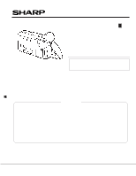
SERVICE MANUAL
LIQUID CRYSTAL CAMCORDER
Hi
8
NTSC
CONTENTS
This document has been published to be used for
after sales service only.
The contents are subject to change without notice.
SHARP CORPORATION
In the interests of user-safety (Required by safety regula-
tions in some countries) the set should be restored to its
original condition and only parts identical to those specified
be used.
MODELS
SERVICE MANUAL
LIQUID CRYSTAL CAMCORDER
Hi
NTSC
8
MODELS
VL-A111U/AH131U/AH151U/AH161U
VL-A111U
VL-AH131U
VL-AH151U
VL-AH161U