Sharp VL-A111UL Service Manual - Page 1

Sharp VL-A111UL Manual

Page 1 highlights

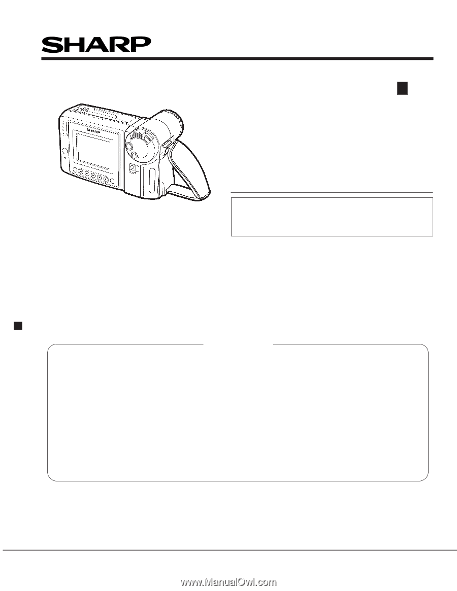
SERVICE MANUAL VL-A111U/AH131U VL-AH151U/AH161U SERVICE MANUAL SY1VL-A111U// LIQUID CRYSTAL CAMCORDER Hi 8 NTSC MODELS VL-A111U VL-AH131U VL-AH151U VL-AH161U In the interests of user-safety (Required by safety regulations in some countries) the set should be restored to its original condition and only parts identical to those specified be used. LIQUID CRYSTAL CAMCORDER Hi 8 NTSC MODELS VL-A111U/AH131U/AH151U/AH161U CONTENTS Page 1. IMPORTANT SERVICE NOTES ...2 2. SPECIFICATIONS ...5 3. PART NAMES AND FUNCTION ...6 4. DISASSEMBLY OF THE SET ...7 5. MECHANISM ADJUSTMENT ...13 6. ADJUSTMENT OF THE ELECTRICAL CIRCUITS 24 7. BLOCK DIAGRAMS ...37 8. SCHEMATIC DIAGRAMS ...46 9.PRINTED WIRING BOARD ASSEMBLIES 92 10.REPLACEMENT PARTS LIST ...103 11.PACKING OF THE SET ...120 SHARP CORPORATION This document has been published to be used for after sales service only. 1The contents are subject to change without notice.

  • 1
  • 2
  • 3
  • 4
  • 5
  • 6
  • 7
  • 8
  • 9
  • 10
  • 11
  • 12
  • 13
  • 14
  • 15
  • 16
  • 17
  • 18
  • 19
  • 20
  • 21
  • 22
  • 23
  • 24
  • 25
  • 26
  • 27
  • 28
  • 29
  • 30
  • 31
  • 32
  • 33
  • 34
  • 35
  • 36
  • 37
  • 38
  • 39
  • 40
  • 41
  • 42
  • 43
  • 44
  • 45
  • 46
  • 47
  • 48
  • 49
  • 50
  • 51
  • 52
  • 53
  • 54
  • 55
  • 56
  • 57
  • 58
  • 59
  • 60
  • 61
  • 62
  • 63
  • 64
  • 65
  • 66
  • 67
  • 68
  • 69
  • 70
  • 71
  • 72
  • 73
  • 74
  • 75
  • 76
  • 77
  • 78
  • 79
  • 80
  • 81
  • 82
  • 83
  • 84
  • 85
  • 86
  • 87
  • 88
  • 89
  • 90
  • 91
  • 92
  • 93
  • 94
  • 95
  • 96
  • 97
  • 98
  • 99

VL-A111U/AH131U
VL-AH151U/AH161U
Page
1. IMPORTANT SERVICE NOTES
.........................................................................................................
2
2. SPECIFICATIONS
..............................................................................................................................
5
3. PART NAMES AND FUNCTION
........................................................................................................
6
4. DISASSEMBLY OF THE SET
............................................................................................................
7
5. MECHANISM ADJUSTMENT
...........................................................................................................
13
6. ADJUSTMENT OF THE ELECTRICAL CIRCUITS
..........................................................................
24
7. BLOCK DIAGRAMS
..........................................................................................................................
37
8. SCHEMATIC DIAGRAMS
.................................................................................................................
46
9.PRINTED WIRING BOARD ASSEMBLIES
.......................................................................................
92
10.REPLACEMENT PARTS LIST
.......................................................................................................
103
11.PACKING OF THE SET
..................................................................................................................
120
SY1VL-A111U//
SERVICE MANUAL
LIQUID CRYSTAL CAMCORDER
Hi
8
NTSC
CONTENTS
This document has been published to be used for
after sales service only.
The contents are subject to change without notice.
SHARP CORPORATION
In the interests of user-safety (Required by safety regula-
tions in some countries) the set should be restored to its
original condition and only parts identical to those specified
be used.
MODELS
SERVICE MANUAL
LIQUID CRYSTAL CAMCORDER
Hi
NTSC
8
MODELS
VL-A111U/AH131U/AH151U/AH161U
VL-A111U
VL-AH131U
VL-AH151U
VL-AH161U