Sharp VL-A111UL Service Manual - Page 10
VL-A111U/AH131U, VL-AH151U/AH161U
 |
View all Sharp VL-A111UL manuals
Add to My Manuals
Save this manual to your list of manuals |
Page 10 highlights
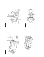
VL-A111U/AH131U VL-AH151U/AH161U (b) LCD unit Connector Lithium PWB Main PWB Connector Inverter transformer (3) Remove two screws ((b)LX-HZ0018TAFF) and two connec- (1) Remove the connector of the Lithium PWB from the Main tors, and remove the LCD unit (with inverter) from the main PWB. body. (2) Move the lithium unit in the direction of the arrow. Tilt frame C Tilt frame V (e) Mechanism unit Battery terminal unit (e) Frame V (e) Connector (1) Disconnect three connectors. Remove the tilt unit from the cabinet of the main body. Connector Main PWB (1) Remove three screws ((e)LX-BZ0191TAFD) and one connector, and remove the frame V from the main body. B C A C E D B A (1) Remove the connector of the speaker cover from the Main D PWB. F (b) (1) Using the slotted precision screwdriver, push and turn the two claws (C and D) which fasten the cassette compartment lid, and the cassette compartment lid will be removed from the hook area of the cassette component. (2) Turning the cassette compartment lid in the arrow direction, lift it, and the claws A and B will be disengaged to remove the cassette compartment lid. Note: (2) Remove the screw ((b)LX-HZ0018TAFF) fixing the speaker Take care to prevent breaking the claws of the cassette com- cover. partment lid. (3) Move the speaker holder in the direction of the arrow to remove it. 10
-
 1
1 -
2
-
3
-
4
-
 5
5 -
 6
6 -
 7
7 -
 8
8 -
 9
9 -
 10
10 -
 11
11 -
 12
12 -
 13
13 -
 14
14 -
 15
15 -
16
-
17
-
18
-
19
-
20
-
21
-
22
-
23
-
24
-
25
-
26
-
27
-
28
-
29
-
30
-
31
-
32
-
33
-
34
-
35
-
36
-
37
-
38
-
39
-
40
-
41
-
42
-
43
-
44
-
45
-
46
-
47
-
48
-
49
-
50
-
51
-
52
-
53
-
54
-
55
-
56
-
57
-
58
-
59
-
60
-
61
-
62
-
63
-
64
-
65
-
66
-
67
-
68
-
69
-
70
-
71
-
72
-
73
-
74
-
75
-
76
-
77
-
78
-
79
-
80
-
81
-
82
-
83
-
84
-
85
-
86
-
87
-
88
-
89
-
90
-
91
-
92
-
93
-
94
-
95
-
96
-
97
-
98
-
99
 |
 |
