Sharp XR10XL PG-MB56X , PG-MB66X Operation Manual - Page 57
Connecting Pin Assignments
 |
UPC - 074000364530
View all Sharp XR10XL manuals
Add to My Manuals
Save this manual to your list of manuals |
Page 57 highlights
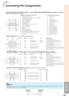
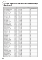
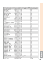
Connecting Pin Assignments COMPUTER-RGB/COMPONENT INPUT1, 2 and COMPUTER-RGB/COMPONENT OUTPUT Terminals: 15-pin mini D-sub female connector COMPUTER-RGB Input/Output 1. Video input (red) 2. Video input (green/sync on green) 3. Video input (blue) 11 15 4. Not connected 5. Not connected 6. Earth (red) 7. Earth (green/sync on green) 8. Earth (blue) 9. Not connected 10. GND 1 5 11. Not connected 6 10 12. Bi-directional data 13. Horizontal sync signal: TTL level 14. Vertical sync signal: TTL level 15. Data clock Component Input/Output 1. PR (CR) 2. Y 3. PB (CB) 4. Not connected 5. Not connected 6. Earth (PR) 7. Earth (Y) 8. Earth (PB) 9. Not connected 10. Not connected 11. Not connected 12. Not connected 13. Not connected 14. Not connected 15. Not connected RS-232C Terminal: 9-pin mini DIN female connector 8 Pin No. Signal Name I/O Reference 9 7 1. Not connected 2. RD Receive Data Input Connected to internal circuit 3. SD Send Data Output Connected to internal circuit 4. Not connected 6 3 5. SG Signal Ground Connected to internal circuit 6. Not connected 7. RS Request to Send Connected to CS in internal circuit 5 4 8. CS Clear to Send Connected to RS in internal circuit 9. 2 1 Not connected RS-232C Terminal: 9-pin D-sub male connector of the DIN-D-sub RS-232C adaptor* (optional accessory: AN-A1RS) * This adaptor is only supplied with PG-MB66X/PG-MB56X/XG-MB50X-L. Pin No. Signal Name I/O Reference 1 5 69 1. 2. RD 3. SD 4. 5. SG 6. 7. RS 8. CS 9. Receive Data Send Data Input Output Signal Ground Request to Send Clear to Send Not connected Connected to internal circuit Connected to internal circuit Not connected Connected to internal circuit Not connected Connected to CS in internal circuit Connected to RS in internal circuit Not connected RS-232C Cable recommended connection: 9-pin D-sub female connector 5 1 96 Pin No. 1. 2. 3. 4. 5. 6. 7. 8. 9. Signal CD RD SD ER SG DR RS CS CI Pin No. 1. 2. 3. 4. 5. 6. 7. 8. 9. Signal CD RD SD ER SG DR RS CS CI Note • Depending on the controlling device used, it may be necessary to connect Pin 4 and Pin 6 on the controlling device (e.g. computer). Projector Computer Pin No. Pin No. 4 4 5 5 6 6 55 Appendix
-
 1
1 -
2
-
3
-
4
-
5
-
6
-
7
-
8
-
9
-
10
-
11
-
12
-
13
-
14
-
15
-
16
-
17
-
18
-
19
-
20
-
21
-
22
-
23
-
24
-
25
-
26
-
27
-
28
-
29
-
30
-
31
-
32
-
33
-
34
-
35
-
36
-
37
-
38
-
39
-
40
-
41
-
42
-
43
-
44
-
45
-
46
-
47
-
48
-
49
-
50
-
51
-
 52
52 -
 53
53 -
 54
54 -
 55
55 -
 56
56 -
 57
57 -
 58
58 -
 59
59 -
 60
60 -
 61
61 -
 62
62 -
63
-
64
-
65
-
66
-
67
-
68
-
69
-
70
 |
 |
