Singer Fashion Mate 5560 User Manual - Page 8
Needle and Presser Foot Area
 |
View all Singer Fashion Mate 5560 manuals
Add to My Manuals
Save this manual to your list of manuals |
Page 8 highlights
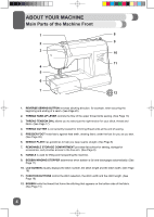
2 ABOUT YOUR MACHINE Needle and Presser Foot Area 1 8 9 2 10 11 3 4 5 12 6 13 7 14 1. THREAD GUIDE controls movement of upper thread. 2. NEEDLE THREADER LEVER is used to engage the automatic needle threader mechanism. 3. NEEDLE THREADER GUIDE holds thread securely before placing it in hook pin. 4. PRESSER FOOT SCREW secures the presser foot holder (shank) onto the presser bar. 5. NEEDLE holds thread during stitch formation. 6. PRESSER FOOT holds fabric against the feed teeth while sewing. Various optional presser feet are available, depending on fabric sewn and sewing techniques. (See Page 9) 7. FEED TEETH (OR FEED DOGS), which look like rows of teeth under the presser foot, control the movement of the fabric under the presser foot. 8. NEEDLE CLAMP holds the machine's needle in position. 9. NEEDLE CLAMP SCREW secures the needle when placed in needle clamp. 10. PRESSER FOOT RELEASE LEVER is pressed to remove the presser foot. (See Page 26) 11. PRESSER BAR accommodates the presser foot holder. 12. PRESSER FOOT HOLDER (OR SHANK) holds presser foot. 13. NEEDLE PLATE covers the bobbin area and provides flat area around presser foot for sewing. 14. STITCHING GUIDELINES are used as a visual reference for guiding fabric straight while sewing. The first line is 3/8" (10mm) from center needle position. The most popular seam allowance measurements are 1/2" (13mm) and 5/8" (16mm). The 1/2" seam allowance is the 2nd line, and the 5/8" seam allowance is the 3rd line from center needle position. 8
-
 1
1 -
2
-
 3
3 -
 4
4 -
 5
5 -
 6
6 -
 7
7 -
 8
8 -
 9
9 -
 10
10 -
 11
11 -
 12
12 -
 13
13 -
14
-
15
-
16
-
17
-
18
-
19
-
20
-
21
-
22
-
23
-
24
-
25
-
26
-
27
-
28
-
29
-
30
-
31
-
32
-
33
-
34
-
35
-
36
-
37
-
38
-
39
-
40
-
41
-
42
-
43
-
44
-
45
-
46
-
47
-
48
-
49
-
50
-
51
-
52
-
53
-
54
-
55
-
56
-
57
-
58
-
59
-
60
-
61
-
62
-
63
-
64
-
65
-
66
-
67
-
68
-
69
-
70
-
71
-
72
-
73
-
74
-
75
-
76
-
77
-
78
-
79
-
80
-
81
-
82
-
83
-
84
-
85
-
86
-
87
-
88
-
89
-
90
-
91
-
92
-
93
-
94
-
95
-
96
-
97
-
98
-
99
-
100
-
101
-
102
-
103
-
104
 |
 |
