Snapper 500Z Operater's Manual - Page 31
Parking Brake Adjustment
 |
View all Snapper 500Z manuals
Add to My Manuals
Save this manual to your list of manuals |
Page 31 highlights
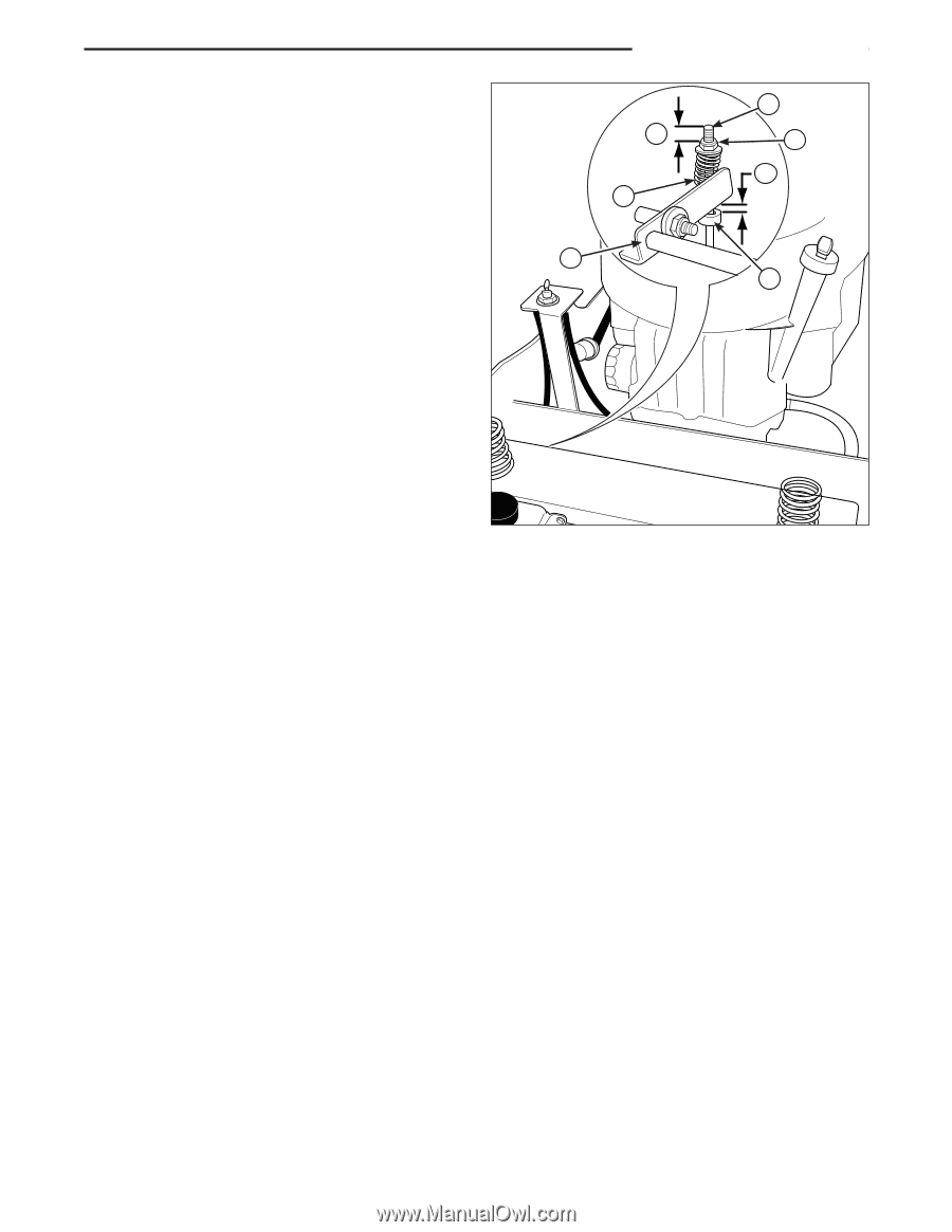
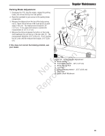
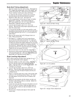
Parking Brake Adjustment 1. Disengage the PTO, stop the engine, engage the parking brake, and remove the key from the ignition. 2. Raise the seat plate to gain access to the parking brake components. 3. Measure the distance from the top of the brake spring rod (C, Figure 34) to the top of the lock nut (D) on both sides of the unit. The measurement should be .50" (1,27 cm). If not, adjust the locknut to achieve the measurement of .50" (1,27 cm) 4. Measure the distance between the bottom of the brake shaft weldment (G) and the top of the set collar (F). The measurement should be .375" (0,95 cm). If not, position the set collar until the measurement equals .375" (0,95 cm). If this does not correct the braking problem, see your dealer. Regular Maintenance B A C D E G F r n Figure 34. Parking Brake Adjustment fo tio A. Brake Spring B. First Measurement - .50" (1,27 cm) C. Brake Spring Rod t c D. Lock Nut E. Second Measurement - .375" (0,95 cm) o u F. Set Collar RNeprodG. Brake Shaft Weldment 29
-
 1
1 -
2
-
3
-
4
-
5
-
6
-
7
-
8
-
9
-
10
-
11
-
12
-
13
-
14
-
15
-
16
-
17
-
18
-
19
-
20
-
21
-
22
-
23
-
24
-
25
-
 26
26 -
 27
27 -
 28
28 -
 29
29 -
 30
30 -
 31
31 -
 32
32 -
 33
33 -
 34
34 -
 35
35 -
 36
36 -
37
-
38
-
39
-
40
-
41
-
42
-
43
-
44
-
45
-
46
-
47
-
48
 |
 |