Snapper 500Z Operater's Manual - Page 34
Warning, Notice, Caution
 |
View all Snapper 500Z manuals
Add to My Manuals
Save this manual to your list of manuals |
Page 34 highlights
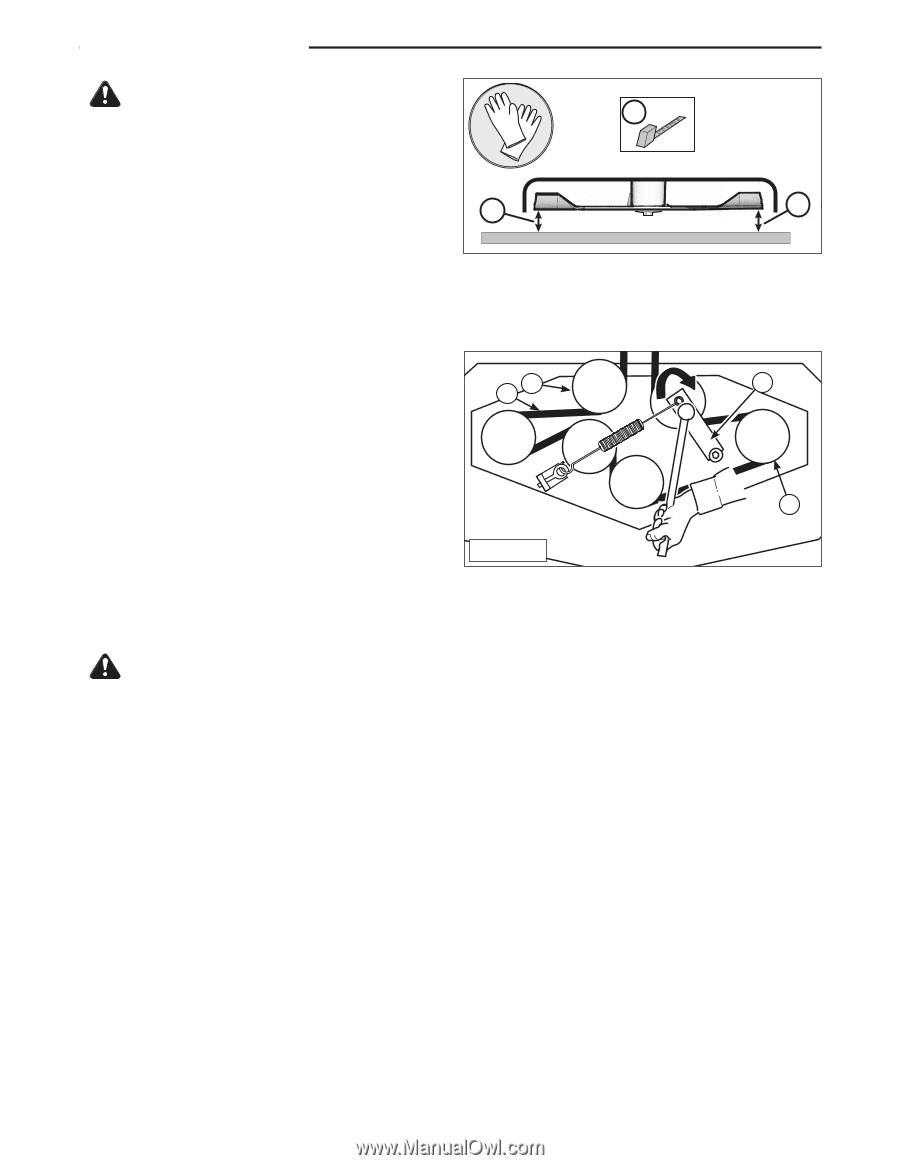
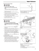
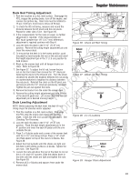
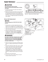
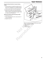
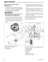
Regular Maintenance CAUTION A Avoid injury! Mower blades are sharp. Always wear gloves when handling blades or working near blades. 7. See Figure 40. Position the outside mower blades so they face front-to-back. A A 8. Measure the front tip of the blade from the cutting edge to the ground. Measure the rear tip of the blade from the cutting edge to the ground. The front measurement should be 4" (10,2 cm), the rear measurement should be Figure 40. Measuring the Blade Height 4-1/4" (10,8 cm). Repeat this process for the other side of the machine. Mower Belt Replacement NOTICE B C To avoid damaging belts, DO NOT PRY BELTS OVER PULLEYS. 1. Park the tractor on a smooth, level surface such as a concrete floor. Disengage the PTO, engage the parking r n brake, turn off the engine, and remove the ignition key. fo tio 2. Lower the mower deck to its lowest cutting position and remove the mower deck guards. 3. Using a 1/2" breaker bar, place the square end in t c the square hole located in the end of the idler arm o (A, Figures 41). Carefully rotate the breaker bar u CLOCKWISE, which will relieve the tension on the belt N d exerted from the idler arm. 48" Model Figure 41. Mower PTO Belt A. Idler Arm B. Stationary Idler Pulley C. Deck Drive Belt D. Spindle Pulley WARNING ro Use extreme caution when rotating the idler arm with the breaker bar, due to the increased tension in the p spring as the idler arm is being rotated. Injury may e result if the breaker bar is prematurely released while R the spring is under tension. 4. Slide the drive belt over the edge of the stationary idler pulley (B). Carefully release the tension on the breaker bar. 5. Remove the old belt and replace with a new one. Make sure the V-side of the belt runs in the pulley grooves. 6. Install the drive belt on the PTO pulley, the spindle pulleys and all idler pulleys except the stationary pulley (B, Figure 41). Carefully rotate the breaker bar CLOCKWISE and install the belt on the stationary idler pulley (B). Carefully release the tension on the breaker bar. 7. Reinstall the mower deck guards. 8. Run the mower under no-load condition for about 5 minutes to break-in the new belt. A D 32 www.SnapperPro.com
-
 1
1 -
2
-
3
-
4
-
5
-
6
-
7
-
8
-
9
-
10
-
11
-
12
-
13
-
14
-
15
-
16
-
17
-
18
-
19
-
20
-
21
-
22
-
23
-
24
-
25
-
26
-
27
-
28
-
 29
29 -
 30
30 -
 31
31 -
 32
32 -
 33
33 -
 34
34 -
 35
35 -
 36
36 -
 37
37 -
 38
38 -
 39
39 -
40
-
41
-
42
-
43
-
44
-
45
-
46
-
47
-
48
 |
 |