Snapper 500Z Operater's Manual - Page 36
Hydraulic Pump Drive Belt, Replacement
 |
View all Snapper 500Z manuals
Add to My Manuals
Save this manual to your list of manuals |
Page 36 highlights
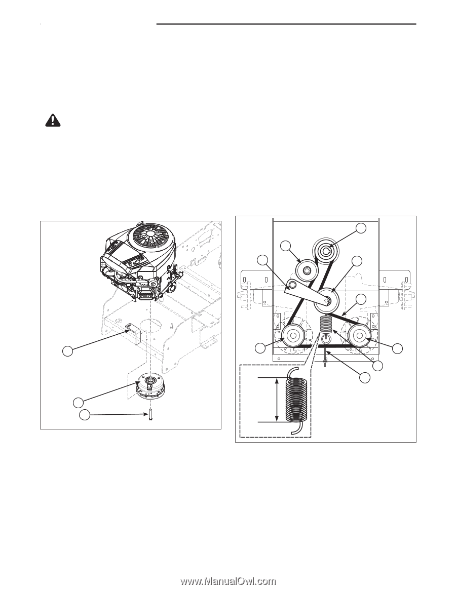
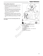
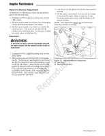
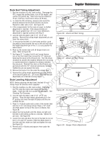
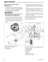
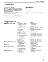
Regular Maintenance Hydraulic Pump Drive Belt Replacement 1. Park the tractor on a smooth, level surface such as a concrete floor. Disengage the PTO, engage the parking brake, turn off the engine, and remove the ignition key. 2. Remove the PTO drive belt (see MOWER BELT REPLACEMENT for removal instructions). WARNING STORED ENERGY DEVICE: Improper release of the belt tension spring can result in personal injury. Use extreme caution when removing this spring. 3. Loosen and remove the crankshaft bolt (C, Figure 43) and the PTO clutch (B) from the engine crankshaft. 4. Loosen the nut on the spring anchor eyebolt (G, Figure 44) to release the majority of the belt tension. Use caution and remove the nut to completely release the tension. 5. Remove the old belt and replace it with the new one. Make sure the V-side of the belt runs in the grooves of the crankshaft pulley and the transmission pulleys (B & C). 6. Reinstall the spring anchor eyebolt (G) into the anchor tab and loosely fasten the nut. Adjust the anchor eyebolt until a measurement of 5-7/8" (14,92 cm) is achieved from the outside if the spring hooks. Tighten nut. 7. Reinstall the PTO clutch to the engine crankshaft and secure with the crankshaft bolt. Tighten the crankshaft bolt to 65 ft. lbs (88 Nm). NOTE: Make sure that the slot in the PTO clutch lines up with the PTO clutch mounting tab (A, Figure 43) underneath the engine deck. 8. Reinstall the PTO drive belt. A B H r n E Not rfooductio C ep 5-7/8" R (14.92 cm) B D A F G C C Figure 43. Removing the PTO Clutch A. PTO Clutch Mounting Tab B. PTO Clutch C. Crankshaft Bolt Figure 44. Hydraulic Pump Drive Belt Replacement A. Pump Drive Belt B. Crankshaft Pulley C. Pump Pulley D. Idler Pulley E. Idler Arm F. Spring G. Spring Anchor Eyebolt H. Stationary Idler Pulley 34 www.Snapper.com
-
 1
1 -
2
-
3
-
4
-
5
-
6
-
7
-
8
-
9
-
10
-
11
-
12
-
13
-
14
-
15
-
16
-
17
-
18
-
19
-
20
-
21
-
22
-
23
-
24
-
25
-
26
-
27
-
28
-
29
-
30
-
 31
31 -
 32
32 -
 33
33 -
 34
34 -
 35
35 -
 36
36 -
 37
37 -
 38
38 -
 39
39 -
 40
40 -
 41
41 -
42
-
43
-
44
-
45
-
46
-
47
-
48
 |
 |