Sony AVD-K600P HTV600DP Operating Instructions (main amp/tuner for HTV) - Page 14
Radio Antenna Connections, Accessory Audio/Video A/V, Connections to DVD/VCR Receiver, Digital - connector
 |
View all Sony AVD-K600P manuals
Add to My Manuals
Save this manual to your list of manuals |
Page 14 highlights
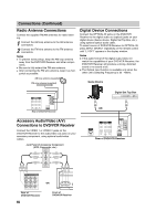
Connections (Continued) Radio Antenna Connections Connect the supplied FM/AM antennas for radio listening. 1 Connect the AM loop antenna to the AM antenna connectors. 2 Connect the FM wire antenna to the FM antenna connectors. Notes To prevent noise pickup, keep the AM loop antenna away from the DVD/VCR Receiver and other components. Be sure to fully extend the FM wire antenna. After connecting the FM wire antenna, keep it as horizontal as possible. AM loop antenna (supplied) FM wire antenna (supplied) Digital Device Connections Connect the OPTICAL IN jacks on the DVD/VCR Receiver to the digital audio out (optical) jacks on your digital device (Game device, Digital Set Top Box, etc.), using optional optical audio cable. To select source of DVD/VCR Receiver to OPTICAL IN, press INPUT SELECT repeatedly on the remote control until "L1 OPT" appears in the display window. Notes If the audio format of the digital output does not match the capabilities of your DVD/VCR Receiver, the DVD/VCR Receiver will produce a strong, distorted sound or no sound at all. The Optical input function is available only when the other unit's Sampling Frequency is 32 - 48kHz. Game Device Digital Set Top Box Rear of DVD/VCR Receiver Accessory Audio/Video (A/V) Connections to DVD/VCR Receiver Connect the VIDEO 1 or VIDEO 2 jacks on the DVD/VCR Receiver to the audio/video out jacks on your accessory component, using optional audio/video cables. Jack Panel of Accessory Component (VCR, Camcorder, etc.) AUDIO OUTPUT R L VIDEO OUTPUT OR Rear of DVD/VCR Receiver OR Rear of DVD/VCR Receiver 14 Front of DVD/VCR Receiver
-
 1
1 -
2
-
3
-
4
-
5
-
6
-
7
-
8
-
 9
9 -
 10
10 -
 11
11 -
 12
12 -
 13
13 -
 14
14 -
 15
15 -
 16
16 -
 17
17 -
 18
18 -
 19
19 -
20
-
21
-
22
-
23
-
24
-
25
-
26
-
27
-
28
-
29
-
30
-
31
-
32
-
33
-
34
-
35
-
36
-
37
-
38
-
39
-
40
-
41
-
42
-
43
-
44
-
45
-
46
-
47
-
48
 |
 |
