Sony CW125 User Manual
Sony CW125 - VPL WXGA LCD Projector Manual
 |
UPC - 027242709096
View all Sony CW125 manuals
Add to My Manuals
Save this manual to your list of manuals |
Sony CW125 manual content summary:
- Sony CW125 | User Manual - Page 1
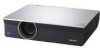
3-211-166-14 (1) Data Projector Operating Instructions VPL-CX100 VPL-CX120/CX125 VPL-CX150/CX155 VPL-CW125 © 2007 Sony Corporation - Sony CW125 | User Manual - Page 2
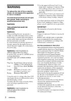
of fire or electric shock, refer servicing to qualified service personnel. WARNING: THIS WARNING IS batteries according to the manufacturer's instructions. For the customers in B digital device, pursuant to Part 15 of the FCC Rules. the equipment off and on, the user is encouraged to try to correct - Sony CW125 | User Manual - Page 3
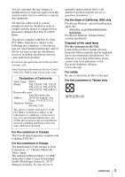
about this product, you may call; Sony Customer Information Service Center 1-800-222-7669 or http://www.sony.com/ Declaration of Conformity Trade Name: SONY Model: VPL-CX100, VPL-CX120, VPL-CX125, VPL-CX150, VPL-CX155, VPL-CW125 Responsible party: Sony Electronics Inc. Address: 16530 Via - Sony CW125 | User Manual - Page 4
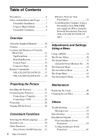
Overview About the Supplied Manuals 10 Features 11 Location When Using the Network Presentation Function) (VPL-CX125/CX155/CW125 only 33 Installing the Projector 21 Connecting the Projector 23 Lamp 46 Cleaning the Air Filter 48 Others Troubleshooting 49 Messages List 53 Specifications - Sony CW125 | User Manual - Page 5
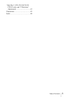
"Side Shot" (VPL-CX125/CX155/ CW125 only) and "V Keystone" Adjustments 63 Dimensions 65 Index 68 Table of Contents 5 - Sony CW125 | User Manual - Page 6
required, consult with qualified Sony personnel. • Should any liquid or solid • Clean the air filter whenever you replace the lamp. • Refer to the "Cleaning the Air Filter" As incorrect maintenance may impair the performance of the projector, take care with respect to the following: • Avoid - Sony CW125 | User Manual - Page 7
may deteriorate or the coating may come off. On LCD projector • The LCD projector is manufactured using high-precision technology. You may, however block-up, the temperature sensor will function with the message "High temp.! Lamp off in 1 min." The power will be turned off automatically after one - Sony CW125 | User Manual - Page 8
preventing the air passing through the filter may cause a rise in the internal temperature of the unit. Clean the air filter whenever you replace the lamp. 8 Notes on Installation and Usage - Sony CW125 | User Manual - Page 9
of preventing theft, by attaching a commercially available theft prevention cable for example. If you lift the projector by holding the Security bar, or hang the projector by using this bar, it may cause the projector to fall or be damaged. Avoid using as the unit tilts more than 20 degrees. Do not - Sony CW125 | User Manual - Page 10
This is an application software for transmitting data from a computer to the projector. This manual contains explanations for the VPL-CX100, VPL-CX120, VPL-CX125, VPL-CX150, VPL-CX155 and VPLCW125 all together. Be aware that the VPL-CX155 is mainly used for explanation of the display, and there may - Sony CW125 | User Manual - Page 11
using a network (VPL-CX125/CX155/CW125 only) Connection to a LAN allows you to turn the projector on/off away from the installation location via a Web browser or to obtain projector status information such as the lamp timer. Side Shot (VPL-CX125/CX155/CW125 only) The projector supports the Side - Sony CW125 | User Manual - Page 12
On-screen menu in 15 languages • Picture/Audio muting • Freeze • Lamp mode switching function • Low power consumption in standby • Security bar About . • Air Shot is a trademark of Sony corporation. • Side Shot is a trademark of Sony corporation. • All other trademarks and registered trademarks - Sony CW125 | User Manual - Page 13
the lens cap before projection. b Front remote control detector c Air filter cover Note To maintain optimal performance, clean the air filter whenever you replace the lamp. For details, see "Cleaning the Air Filter" on page 48. Location and Function of Controls (Main Unit) 13 - Sony CW125 | User Manual - Page 14
see "Control Panel" on page 15. e Ventilation holes (exhaust) f Adjuster adjustment button For details, see "Using the adjuster" on page 27. g Lamp cover h Ventilation holes (intake) i Adjusters j Rear remote control detector k Connector/Connector Panel For details, see "Connector Panel" on page 16 - Sony CW125 | User Manual - Page 15
lamp has reached the end of its life or reaches a high temperature. For details, see page 51. b ON/STANDBY indicator Lights up or flashes under the following conditions: - Lights in red when the AC power cord is plugged into a wall outlet. Once the projector of models VPL-CX125/ CX155/CW125, Side - Sony CW125 | User Manual - Page 16
CW125 only) NETWORK connector (RJ-45) Connects to the LAN cable when the network function is in use. CAUTION For safety, do not connect the connector for peripheral device wiring that might have excessive voltage to this port. Follow the instructions for this port. b INPUT A Analog RGB connector (HD - Sony CW125 | User Manual - Page 17
AC power cord. e OUTPUT MONITOR connector (HD D-sub 15-pin, female) Connect to projector from the computer. Remote Commander The supplied remote commander differs according to the model. Refer to the relevant page. VPL-CX125/CX155/CW125: Page 17. VPL-CX100/CX120/CX150: Page 19. VPL-CX125/CX155/CW125 - Sony CW125 | User Manual - Page 18
c AIR SHOT key Displays the Network Presentation Home. For details, see Operating Instructions for Network (stored on the CD-ROM). d 42. l CONTROL S OUT jack (stereo mini-jack) This function is not provided in this projector. m MUTING keys Cut off the picture and sound. • PIC: Cuts off the picture. - Sony CW125 | User Manual - Page 19
detector. • The operation range is limited. The shorter the distance between the Remote Commander and the projector is, the wider the angle within which the commander can control the projector becomes. VPL-CX100/CX120/CX150 The keys that have the same names as those on the control panel function - Sony CW125 | User Manual - Page 20
Remote Commander operation • Make sure that nothing obstructs the infrared beam between the Remote Commander and the remote control detector on the projector. Direct the Remote Commander toward the remote control detector. • The operation range is limited. The shorter the distance between the Remote - Sony CW125 | User Manual - Page 21
Projector The distance between the lens and the screen varies depending on the size of the projected image. Use the following table as a guide. Screen Projecting the Picture Distance between the screen and the center of the lens VPL shown in the table above. VPL-CW125 (When "Aspect" on the - Sony CW125 | User Manual - Page 22
a slight difference between the actual value and the design value shown in the table above. Notes for VPL-CW125 only • When "Aspect" on the Signal menu is set to other than "Full 2", black bands 2" size. For details on installation, see "Installation Diagram" on page 59. 22 Installing the Projector - Sony CW125 | User Manual - Page 23
itself. For VPL-CX125/CX155/CW125, when connecting to a LAN using a LAN cable, see "Operating Instructions for Network" stored on the CD-ROM. Connecting a Computer This section describes how to connect the projector to a computer. For more information, refer to the computer's instruction manual. To - Sony CW125 | User Manual - Page 24
CX155) or WXGA (VPL-CW125) for the external monitor. • If you set your computer, such as a to connect the projector to a VCR. For more information, refer to the instruction manuals of the equipment you are connecting. To connect to a video or S video output connector Side NETWORK INPUT C RGB - Sony CW125 | User Manual - Page 25
output connector Side NETWORK INPUT C RGB supplied) (Use a no-resistance cable.) B Signal Cable (not supplied) HD D-sub 15-pin (male) ↔ 3 × phono jack Notes • Set you connect the projector to a video GBR output connector, select "Video GBR" or when you connect the projector to a component - Sony CW125 | User Manual - Page 26
Projecting 24 LAMP/ COVER ON/ STANDBY INPUT KEYSTONE MENU PUSH ENTER PIC in green. 3 Turn on the equipment connected to the projector. 4 Select the input source. To operate with the Remote Commander of VPL-CX125/ CX155/CW125 You can select directly the input signal you want to project - Sony CW125 | User Manual - Page 27
LCD type, you may have to switch the computer to output to the projector by pressing certain keys (e.g., , etc.), or by changing your computer's settings. Projecting the Picture * VPL-CX125/CX155/CW125 to use the network presentation function Input-C (VPLCX125/ CX155/ CW125 only) Video equipment - Sony CW125 | User Manual - Page 28
depending on the room temperature or the screen angle. In this case, adjust it manually. Press the KEYSTONE key to "V Keystone" displays on the screen, and adjust the value with the v/V/b/B keys. • Be careful not to let the projector down on your fingers. • Do not push hard on the top of the - Sony CW125 | User Manual - Page 29
Functions ON/STANDBY 2 indicator 3 4,5,6 LAMP/ COVER ON/ STANDBY INPUT KEYSTONE MENU ZOOM SHIFT ASPECT KEY STONE VPL-CX125/CX155/CW125 MPUITICNG PEUNSTHER MENU KEYSTONE INPUT VPL-CX100/CX120/CX150 1 Plug the AC power cord into a wall outlet. 2 Press the ?/1 key to turn on the projector - Sony CW125 | User Manual - Page 30
key. The menu also disappears automatically if a key is not pressed for one minute. Security Lock The projector is equipped with a security lock function. When you turn the power of the projector on, you are required to input the previously set password. If you do not input the correct password - Sony CW125 | User Manual - Page 31
password on this screen. 3 Enter the password again to confirm. Note If you call the customer service center because you have forgotten the password, you will need to be able to verify the projector's serial number and your identity. (This process may differ in other countries/regions.) Once your - Sony CW125 | User Manual - Page 32
on and off, set the direct power on function to "On." You can turn the power on/off without pressing the power key on the projector. Effective Tools for Your Presentation To enlarge the image (Digital Zoom function) You can select a section of the image to enlarge. This function works when - Sony CW125 | User Manual - Page 33
(When Using the Network Presentation Function) (VPLCX125/CX155/CW125 only) When you are using the network presentation function to any obstruction between the presentation tool and the remote control detector on the projector, the presentation tool may not function properly. • A black screen may - Sony CW125 | User Manual - Page 34
a MENU The projector is equipped with Function Status: Language: Input-A Signal Sel.: Color System: Lamp Timer Reset Installation Setup Information Sel: Set: On English explanations for VPL-CX100, VPL-CX120, VPL-CX125, VPL-CX150, VPL-CX155 and VPL-CW125 all together in this manual. Be please - Sony CW125 | User Manual - Page 35
of the Signal menu • "Side Shot" on the Installation menu (VPL-CX125/CX155/CW125 only) Storage of the settings The settings are automatically stored in the projector memory when the ENTER key is pressed. Note The resetting item of the Lamp timer setting is not memorized. If no signal is input If - Sony CW125 | User Manual - Page 36
a computer signal • High: Makes white part bluish. • Middle: Makes white part reddish. • Low: Makes white part greenish. When a video signal • High: Turns white part to a bluish and cool tone. • Middle: Turns white part o a natural tone. • Low: Turns white part to a reddish and warm tone. Adjusts - Sony CW125 | User Manual - Page 37
Setting items Adjust Signal... Dot Phase H Size Shift Aspect (When the video signal is input) Functions Initial setting Adjusts the dot phase of the LCD panel and the signal output from a computer. Adjust the picture further for finer picture after the picture is adjusted by pressing the APA key - Sony CW125 | User Manual - Page 38
input picture element to that of the LCD. The picture will be clear but projector has 43 types (VPL-CX100/ CX120/CX125/CX150/CX155) or 44 types (VPL-CW125 user memory items are registered, the newest memory always overwrites the oldest one. Signal Super Mac-2 SGI-1 Macintosh 19" Macintosh 21" Sony - Sony CW125 | User Manual - Page 39
the APA key on the Remote Commander. When set to "On," the projector detects input signals in Off the following order: Input A, B, *C/Video/S-Video. It indicates the input channel when the INPUT key is pressed. *VPL-CX125/CX155/CW125 only When set to "On," a test pattern is displayed on the Off - Sony CW125 | User Manual - Page 40
Lamp off: The lamp goes off if no signal is input for 10 minutes. The lamp lights again when a signal is input or any key is pressed. • Standby: The projector adjust the picture manually. • When "Standby mode" is set to "Low", the network presentation and the network control functions cannot be - Sony CW125 | User Manual - Page 41
VPL-CX125/ CX155/CW125 only) Image Flip Background Lamp Mode IR Receiver Functions Initial setting Corrects the trapezoidal distortion caused by the projection angle. Select "Auto" for automatic correction, or "Manual" for manual rear of the projector. • Front - Sony CW125 | User Manual - Page 42
Initial setting ID Mode (VPL-CX125/ CX155/CW125 only) Assigns an ID number (1 to 3) to the projector when you All want control two or more projectors individually with the supplied Remote Commander. When this item is set to "1," you can control the projector with the Remote Commander with - Sony CW125 | User Manual - Page 43
color system of the input signal. If you select "Auto," the projector detects the color system of the input signal automatically. If the picture is system cannot be detected. Auto Lamp Timer Reset When replacing the lamps, reset the lamp timer. - Adjustments and Settings Using a Menu The - Sony CW125 | User Manual - Page 44
input signal. Displays the type of the input signal. Indicates how long the lamp has been turned on. Notes • Horizontal frequency and Vertical frequency may not be displayed depending on the input signal used on the projector. • You cannot change the displays listed above. 44 The Information Menu - Sony CW125 | User Manual - Page 45
58 and NTSC4.43 only, except B & W *3: Preset memory No. 3, 4 only. *4: VPL-CX125/CX155/CW125 only. Signal menu Input signal Video GBR Computer z z z z z z z - z - z z z - z*3 z Network*4 z z z - - z - z Item Video/S-Video Component (Y/C) Aspect z z Adjust Signal Dot Phase - Sony CW125 | User Manual - Page 46
of use. Use an LMP-C200 Projector Lamp as the replacement lamp. Use of lamps other than the LMP-C200 may cause damage to the projector. Note If the lamp breaks, consult with qualified Sony personnel for replacing the lamp and internal checking. 1 Turn off the projector, and disconnect the AC power - Sony CW125 | User Manual - Page 47
the menu screen. Note To erase a message, press any key on the control panel of the projector or on the Remote Commander. Note Be sure to attach the lamp cover securely as it was. If not, the projector cannot be turned on. (Page 51) 7 Connect the power cord. The ON/STANDBY indicator lights - Sony CW125 | User Manual - Page 48
lamp. Remove the air filter, and then remove the dust with a vacuum cleaner. The time needed to clean the air filter will vary depending on the environment or how the projector one. For details on new air filter, consult with qualified Sony personnnel. • Be sure to attach the air filter cover firmly - Sony CW125 | User Manual - Page 49
Troubleshooting If the projector appears to be operating erratically, try to diagnose and correct the problem using the following instructions. If the problem persists, consult with qualified Sony the computer and the numbers of pixels on the LCD panel. c Change the desktop pattern on the connected - Sony CW125 | User Manual - Page 50
lamp with a new one (see page 46). The picture is not clear. • The picture is out of focus. c Adjust the focus (see page 28). • Condensation has accumulated on the lens. c Leave the projector the AUDIO MUTING key (VPL-CX100/CX120/CX150 or MUTING (AUDIO) key (VPL-CX125/CX155/CW125) to release audio - Sony CW125 | User Manual - Page 51
Mode" in the Installation menu does not match the ID number of the ID MODE keys on the Remote Commander. (VPL-CX125/CX155/CW125 only) c Assigns the same ID number to the projector and the Remote Commander, or set "ID Mode" in the Installation menu to "All" (see pages 18, 42). Others Symptom - Sony CW125 | User Manual - Page 52
cord from the wall outlet after the ON/ STANDBY indicator goes out, plug the power cord to the wall outlet, and then turn the projector on again. If the ON/STANDBY flashes in red and the problem persists, the electrical system has failed. c Consult with qualified Sony personnel. 52 Troubleshooting - Sony CW125 | User Manual - Page 53
of the messages displayed on the screen. Message Meaning and Remedy High temp.! Lamp off in 1 The internal temperature is too high. min. c Turn off control panel of the projector are locked. Operate the projector with the keys on the Remote Commander (see page 40). Others Troubleshooting 53 - Sony CW125 | User Manual - Page 54
Specifications Optical characteristics Projection system 3 LCD panels, 1 lens, 3 primary color shutter system LCD panel VPL-CX100/CX120/CX125/ CX150/CX155: 0.79-inch XGA panel, 2,359,296 pixels (1024 × 768 × 3) VPL-CW125: 0.74-inch WXGA signals of the projector. Applicable video signals - Sony CW125 | User Manual - Page 55
temperature -20°C to +60°C (-4°F to +140°F) Storage humidity 10% to 90% Supplied accessories Remote Commander (1) Size AA (R6) batteries (2) (VPLCX125/CX155/CW125) Lithium battery CR2025 (1) (VPLCX100/CX120/CX150) Lens cap (1) HD D-sub 15 pin cable (2 m) (1) (1-791-992-xx) Specifications 55 Others - Sony CW125 | User Manual - Page 56
power cord (1) CD-ROM (Operating Instructions, Application Software) (1) Quick Reference Manual (1) Safety Regulations (1) Security Label (1) Design and specifications are subject to change without notice. Note Always verify that the unit is operating properly before use. SONY WILL NOT BE LIABLE FOR - Sony CW125 | User Manual - Page 57
, V-pos H-pos, V-pos SIZE - - - - - - - - - - 800 832 848 800 832 800 864 832 840 832 1024 1056 1040 1056 1048 1152 1344 1328 1312 1376 Others Specifications 57 - Sony CW125 | User Manual - Page 58
(Input A connector) Video GBR (Input A connector) Computer (Input A, Input B connector) Preset memory No. 1, 2 3-11 3-11 21-50, 55, 56, 60, 63*1 *1: VPL-CW125 only Note When a signal other than the preset signals shown above is input, the picture may not be displayed properly. 58 Specifications - Sony CW125 | User Manual - Page 59
15.9 (21/32) Center of the screen Center of the lens Floor Unit: mm (inches) This section describes the examples of installing the projector on a desk, etc. See the chart on page 60 concerning the installation measurements. The alphabetical letters in the illustration indicate the distances below - Sony CW125 | User Manual - Page 60
171/0.7292)-45.650} × 0.975 b = x-(PS/0.7292 × 4.68) c = x-(PS/0.7292 × 4.68+61.2) Notes for VPL-CW125 only • The projected image size is the one when "Aspect" on the Signal menu is set to "Full 2". When "Aspect" the adjusters of the projector x: free N: minimum M: maximum 60 Installation Diagram - Sony CW125 | User Manual - Page 61
Unit: mm (inches) This section describes the examples for installing the projector on the ceiling. When installing the projector on the ceiling, use a Projector Suspension Support recommended by Sony. For ceiling installation, ask for qualified Sony personnel. See the chart on page 62 concerning the - Sony CW125 | User Manual - Page 62
× 0.975 x = b + (PS/0.7874 × 4.667+53.2) VPL-CW125 (When "Aspect" on the Signal menu is set to "Full 2") projector suspension support on bottom surface of this projector and the center of the screen b: distance between the projector suspension support mounting surface on bottom of this projector - Sony CW125 | User Manual - Page 63
"V Keystone" The adjustable distortion area using "Side Shot" and "V Keystone" is described below. Screen a a b b a: Tilting angle of the projector in the "V Keystone" adjustment area b: "Side Shot" (H Keystone adjustment) area "Side Shot" (VPL-CX125/CX155/CW125 only) and "V Keystone" Adjustments 63 - Sony CW125 | User Manual - Page 64
0 +/-18 +/-25 b +/-15 +/-8 0 +/-13 +/-8 0 +/-13 +/-6 0 +/-11 +/-6 0 +/-7 +/-4 0 VPL-CW125 Input signals Video/60, Video/50, 480/60i, 575/50i, 480/60p, 575/50p 1080/60i, 1080/50i, 540 Manual," and correct the distortion using input values. 64 "Side Shot" (VPL-CX125/CX155/CW125 only) and - Sony CW125 | User Manual - Page 65
(Front) 64.9 (2 5/8) 61.2 (2 1/2) 27 13 (17/32) (1 1/8) Top 24 (31/32) 141 (5 5/8) 123 (4 7/8) 34 (1 3/8) Unit: mm (inches) 5.3 (7/32) DATA PROJECTOR LAMP/ COVER ON/ STANDBY INPUT KEYSTONE MENU PUSH ENTER PIC MUTING 298 (11 3/4) 263 (10 3/8) Others 265 (10 1/2) 372 (14 3/4) Unit - Sony CW125 | User Manual - Page 66
16) 103 (4 1/8) 260 (10 1/4) VPL-CX125/CX155/CW125 only 172 (6 7/8) NETWORK INPUT C RGB AUDIO INPUT A RGB AUDIO INPUT B MONITOR AUDIO OUTPUT S VIDEO VIDEO AUDIO VIDEO IN RS-232C REMOTE 8 (11/32) 16 (21/32) 78 (3 1/8) 18 (23/32) Projector suspension support mounting surface 17 (11 - Sony CW125 | User Manual - Page 67
66 (2 5/8) 326 (12 7/8) 148 (5 7/8) 174 (6 7/8) 32 (1 5/16) 15 (19/32) Unit: mm (inches) 137.3 (5 1/2) 124 (5) 275 (10 7/8) Others 104.5 (4 1/8) Holes for mounting a projector suspension support 56.6 (2 1/4) 46.1 (1 7/8) 12.2 (1/2) Center of the projector Unit: mm (inches) Dimensions 67 - Sony CW125 | User Manual - Page 68
59 Installing the projector 21 IR Receiver 41 L Lamp Mode 41 Lamp Timer 44 Lamp Timer Reset 43 LAMP/COVER indicators 15 53 Warning messages 53 Model name 44 O ON/STANDBY indicator 15 Optional accessories 56 P Panel Key Lock 40 Picture Mode 36 Pin assignment 56 Power Saving - Sony CW125 | User Manual - Page 69
Security lock 14 Serial number 44 Sharpness 36 Shift 37 Side Shot 41, 63 Signal type 44 Smart APA 39 Speaker 39 Specifications 54 Standby Mode 39 Start Up Image 39 Status 43 Supplied accessories 55 T Test Pattern 39 Troubleshooting 49 V V Keystone 41, 63 Volume 36 Index 69 Others - Sony CW125 | User Manual - Page 70
Sony Corporation
-
 1
1 -
 2
2 -
 3
3 -
 4
4 -
 5
5 -
 6
6 -
 7
7 -
8
-
9
-
10
-
11
-
12
-
13
-
14
-
15
-
16
-
17
-
18
-
19
-
20
-
21
-
22
-
23
-
24
-
25
-
26
-
27
-
28
-
29
-
30
-
31
-
32
-
33
-
34
-
35
-
36
-
37
-
38
-
39
-
40
-
41
-
42
-
43
-
44
-
45
-
46
-
47
-
48
-
49
-
50
-
51
-
52
-
53
-
54
-
55
-
56
-
57
-
58
-
59
-
60
-
61
-
62
-
63
-
64
-
65
-
66
-
67
-
68
-
69
-
70
 |
 |
3-211-166-
14
(1)
Data Projector
Operating Instructions
VPL-CX100
VPL-CX120/CX125
VPL-CX150/CX155
VPL-CW125
© 2007 Sony Corporation