Sony CW125 User Manual - Page 16
Connector Panel, MENU key, PUSH ENTER, Arrow, PIC MUTING key, INPUT C VPL-CX125/CX155, CW125 only - vpl hd
 |
UPC - 027242709096
View all Sony CW125 manuals
Add to My Manuals
Save this manual to your list of manuals |
Page 16 highlights
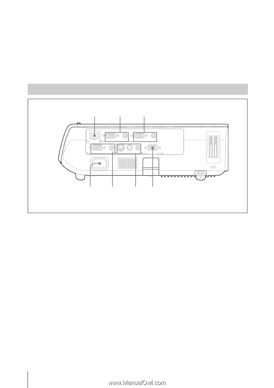
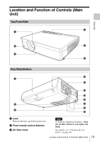
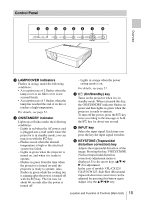
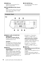
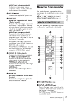
f MENU key Displays the on-screen menu. Press again to clear the menu. g PUSH ENTER/v/V/b/B (Arrow) keys Used to enter the settings of items in the menu system, select a menu, or make various adjustments. h PIC MUTING key Cuts off the picture. Press again to restore the picture. Connector Panel Side 1 2 3 NETWORK INPUT C RGB AUDIO INPUT A RGB AUDIO INPUT B MONITOR AUDIO S VIDEO VIDEO AUDIO OUTPUT VIDEO IN RS-232C REMOTE 4 5 67 a INPUT C (VPL-CX125/CX155/ CW125 only) NETWORK connector (RJ-45) Connects to the LAN cable when the network function is in use. CAUTION For safety, do not connect the connector for peripheral device wiring that might have excessive voltage to this port. Follow the instructions for this port. b INPUT A Analog RGB connector (HD D-sub 15-pin, female) Inputs a computer signal, video GBR signal, component signal, or DTV signal depending on the connected equipment. Connects to the output connector of equipment using the supplied cable or an optional cable. For details, see "Connecting a Computer" on page 23 and "Connecting a VCR" on page 24. AUDIO jack (stereo minijack) To listen to sound output from a computer, connect via this jack to the audio output of the computer. For details, see "Connecting a Computer" on page 23 and "Connecting a VCR" on page 24. c INPUT B Analog RGB connector (HD D-sub 15-pin, female) Connect to external equipment such as a computer. Connects to the monitor output of a computer using the supplied cable or an optional cable. 16 Location and Function of Controls (Main Unit)
-
 1
1 -
2
-
3
-
4
-
5
-
6
-
7
-
8
-
9
-
10
-
 11
11 -
 12
12 -
 13
13 -
 14
14 -
 15
15 -
 16
16 -
 17
17 -
 18
18 -
 19
19 -
 20
20 -
 21
21 -
22
-
23
-
24
-
25
-
26
-
27
-
28
-
29
-
30
-
31
-
32
-
33
-
34
-
35
-
36
-
37
-
38
-
39
-
40
-
41
-
42
-
43
-
44
-
45
-
46
-
47
-
48
-
49
-
50
-
51
-
52
-
53
-
54
-
55
-
56
-
57
-
58
-
59
-
60
-
61
-
62
-
63
-
64
-
65
-
66
-
67
-
68
-
69
-
70
 |
 |