Sony DVP-K85P Operating Instructions - Page 21
L1AC - Step 4: Connecting the Audio Cords
 |
View all Sony DVP-K85P manuals
Add to My Manuals
Save this manual to your list of manuals |
Page 21 highlights
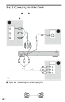
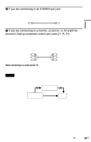
Hookups Step 4: Connecting the Audio Cords Select one of the following patterns A or B, according to the input jack on your TV monitor, projector, or AV amplifier (receiver). This will enable you to listen to sound. (red) (white) Audio/video cord (supplied) (yellow)* (white) (yellow)* (red) INPUT A VIDEO L AUDIO R LINE OUT R AUDIO L VIDEO to LINE OUT L/R (AUDIO) COAXIAL LINE OUT R AUDIO L VIDEO OPTICAL DIGITAL OUT Y PB PR COMPONENT VIDEO OUT S VIDEO OUT to DIGITAL OUT (COAXIAL or OPTICAL) COAXIAL TV, projector, or AV amplifier (receiver) CD/DVD player OPTICAL DIGITAL OUT Optical digital cord (not supplied) [Speakers] Rear (L) to optical digital input Coaxial digital cord (not supplied) to coaxial digital input B [Speakers] Rear (R) Front (L) Center AV amplifier (receiver) with a decoder Front (R) Subwoofer : Signal flow * The yellow plug is used for video signals (page 18). z Hint For correct speaker location, see the operating instructions supplied with the connected components. ,continued 21US
-
 1
1 -
2
-
3
-
4
-
5
-
6
-
7
-
8
-
9
-
10
-
11
-
12
-
13
-
14
-
15
-
 16
16 -
 17
17 -
 18
18 -
 19
19 -
 20
20 -
 21
21 -
 22
22 -
 23
23 -
 24
24 -
 25
25 -
 26
26 -
27
-
28
-
29
-
30
-
31
-
32
-
33
-
34
-
35
-
36
-
37
-
38
-
39
-
40
-
41
-
42
-
43
-
44
-
45
-
46
-
47
-
48
-
49
-
50
-
51
-
52
-
53
-
54
-
55
-
56
-
57
-
58
-
59
-
60
-
61
-
62
-
63
-
64
-
65
-
66
-
67
-
68
-
69
-
70
-
71
-
72
-
73
-
74
-
75
-
76
-
77
-
78
-
79
-
80
-
81
-
82
-
83
-
84
-
85
-
86
-
87
-
88
-
89
-
90
-
91
-
92
-
93
-
94
-
95
-
96
 |
 |
