Sony HCD-D670AV Service Manual - Page 12
Deck A is RV311 L-CH and RV411 R-CH, deck B is RV301 L, Press the DISPLAY/DEMO button
 |
View all Sony HCD-D670AV manuals
Add to My Manuals
Save this manual to your list of manuals |
Page 12 highlights
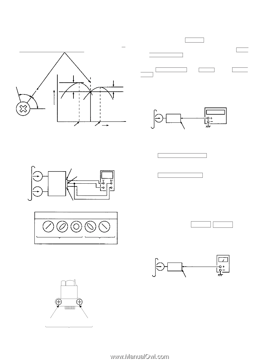
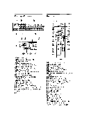
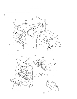
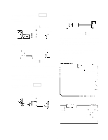
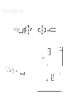
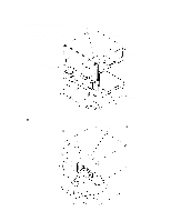
2. Turn the adjustment screw and check output peaks. If the peaks do not match for L-CH and R-CH, turn the adjustment screw so that outputs match within 1 dB of peak. L-CH peak output within level 1dB within 1dB screw position R-CH peak L-CH peak R-CH peak screw position 3. Mode : Playback (FWD) test tape P-4-A100 (10kHz, -10dB) set main board CN403 Pin 3 Pin 2 L R oscilloscope Pin 1 Waveform of oscilloscope in phase 45° good 90° 135° 180° wrong 4. Repeat steps 1 to 3 in playback (REV) mode. 5. After the adjustments, apply suitable locking compound to the parts adjusted. Adjustment Location : Record/Playback Head (Deck A and B) FWD side REV side Adjustment screw Tape Speed Adjustment DECK A NOTE : Start the tape speed adjustment as bellow after setting the test mode.The tape speed can be changed with the HIGH SPEED DUBBING button during the test mode. Method : 1. Turn the power switch on. 2. Press the DISPLAY/DEMO button, MENU 1 button and TUNER/ BAND button simulateously. Procedure : Mode : Playback (FWD) test tape WS-48B (3kHz, 0dB) frequency counter set main board CN403 (Pin 3 : L-CH) (Pin 1 : R-CH) 1. Insert tha WS-48B into the deck A to playback. 2. Press the HIGH SPEED DUBBING button. Then at HIGH SPEED mode. 3. Adjust RV652 on the MD board so that the frequency counter reading becomes 6,000 ± 30 Hz. 4. Press the HIGH SPEED DUBBING button again to be set the NORMAL SPEED mode. 5. Set to the playback mode. 6. Adjust RV651 on the MD board so that the frequency counter reading becomes 3,000 ± 15 Hz. Frequency difference between deck A and deck B the beginning of the tape should be within ± 1.5%. Adjustment Location : MD board Playback Level Adjustment DECK A DECK B Procedure : Mode : Playback (FWD) test tape P-4-L300 (315Hz, 0dB) level meter set main board CN403 (Pin 3 : L-CH) (Pin 1 : R-CH) Deck A is RV311 (L-CH) and RV411 (R-CH), deck B is RV301 (LCH) and RV401 (R-CH) so that adjustment within the following adjustment level. Adjustment level : CN403 PB level : 301.5 to 338.3 mV (-8.2 to -7.2 dB) level difference between the channels : within ± 0.5 dB Adjustment Location : MD board - 12 -
-
 1
1 -
2
-
3
-
4
-
5
-
6
-
 7
7 -
 8
8 -
 9
9 -
 10
10 -
 11
11 -
 12
12 -
 13
13 -
 14
14 -
 15
15 -
 16
16 -
 17
17 -
18
-
19
-
20
-
21
-
22
-
23
-
24
-
25
-
26
-
27
-
28
-
29
-
30
-
31
-
32
-
33
-
34
-
35
-
36
-
37
-
38
-
39
-
40
-
41
-
42
-
43
-
44
-
45
-
46
-
47
-
48
-
49
-
50
-
51
-
52
-
53
-
54
-
55
-
56
-
57
-
58
-
59
-
60
-
61
-
62
-
63
-
64
-
65
-
66
-
67
-
68
-
69
-
70
-
71
-
72
-
73
-
74
-
75
-
76
-
77
-
78
 |
 |