Sony HCD-D670AV Service Manual - Page 4
SERVICING NOTE, FL Display Tube, LED All Lit and Key Check mode]
 |
View all Sony HCD-D670AV manuals
Add to My Manuals
Save this manual to your list of manuals |
Page 4 highlights
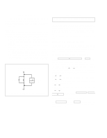
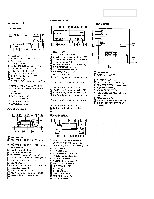
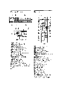
SAFETY CHECK-OUT After correcting the original service problem, perform the following safety checks before releasing the set to the customer: Check the antenna terminals, metal trim, "metallized" knobs, screws, and all other exposed metal parts for AC leakage. Check leakage as described below. LEAKAGE The AC leakage from any exposed metal part to earth ground and from all exposed metal parts to any exposed metal part having a return to chassis, must not exceed 0.5 mA (500 microampers). Leakage current can be measured by any one of three methods. 1. A commercial leakage tester, such as the Simpson 229 or RCA WT-540A. Follow the manufacturers' instructions to use these instruments. 2. A battery-operated AC milliammeter. The Data Precision 245 digital multimeter is suitable for this job. 3. Measuring the voltage drop across a resistor by means of a VOM or battery-operated AC voltmeter. The "limit" indication is 0.75 V, so analog meters must have an accurate low-voltage scale. The Simpson 250 and Sanwa SH-63Trd are examples of a passive VOM that is suitable. Nearly all battery operated digital multimeters that have a 2V AC range are suitable. (See Fig. A) To Exposed Metal Parts on Set 0.15µF 1.5kΩ AC voltmeter (0.75V) Earth Ground Fig. A. Using an AC voltmeter to check AC leakage. SERVICING NOTE NOTES ON HANDING THE OPTICAL PICK-UP BLOCK OR BASE UNIT The laser diode in the optical pick-up block may suffer electrostatic break-down because of the potential difference generated by the charged electrostatic load, etc. on clothing and the human body. During repair, pay attention to electrostatic break-down and also use the procedure in the printed matter which is included in the repair parts. The flexible board is easily damaged and should be handled with care. NOTES ON LASER DIODE EMISSION CHECK The laser beam on this model is concentrated so as to be focused on the disc reflective surface by the objective lens in the optical pick-up block. Therefore, when checking the laser diode emission, observe from more than 30 cm away from the objective lens. [FL Display Tube, LED All Lit and Key Check mode] When the TUNER/BAND , DISPLAY/DEMO , and FILE 2 buttons are pressed simultaneously, the FL display tube and LEDs will all light up. Press any button to enter the key check mode. When the key check mode is entered, the FL display tube displays "K 1 J0 V0". Each time a button is pressed, the counter increases in the following order, K 2 n K 3 n K 4. If buttons already pressed once are pressed again, the counter will not increase. When the VOLUME knob is rotated in the + direction, the count increases in the following order. V1 n V2 n V3. When rotated in the - direction, it decreases in the following order. V0 n V9 n V8. When the AMS dial is rotated in the clockwise direction, the count increases in the following order. J1 n J2 n J3. When rotated in the counterclockwise direction, it decreases in the following order. J0 n J9 n J8. To exit form the test mode, press the TUNER/BAND , DISPLAY/ DEMO , FILE 2 buttons simultaneously again. [Switching the channel step 9 KHz/10 KHz] Press ENTER/NEXT button and POWER button simultaneously to switch the AM channel step 9 kHz and 10 kHz. Be sure not to change with carelessness. - 4 -
-
 1
1 -
 2
2 -
 3
3 -
 4
4 -
 5
5 -
 6
6 -
 7
7 -
 8
8 -
 9
9 -
 10
10 -
11
-
12
-
13
-
14
-
15
-
16
-
17
-
18
-
19
-
20
-
21
-
22
-
23
-
24
-
25
-
26
-
27
-
28
-
29
-
30
-
31
-
32
-
33
-
34
-
35
-
36
-
37
-
38
-
39
-
40
-
41
-
42
-
43
-
44
-
45
-
46
-
47
-
48
-
49
-
50
-
51
-
52
-
53
-
54
-
55
-
56
-
57
-
58
-
59
-
60
-
61
-
62
-
63
-
64
-
65
-
66
-
67
-
68
-
69
-
70
-
71
-
72
-
73
-
74
-
75
-
76
-
77
-
78
 |
 |
