Sony HCD-D670AV Service Manual - Page 14
FM Tuned Level Adjustment, Adjustment Location, AEP, UK, G, IT model, TCB BOARD], Other model
 |
View all Sony HCD-D670AV manuals
Add to My Manuals
Save this manual to your list of manuals |
Page 14 highlights
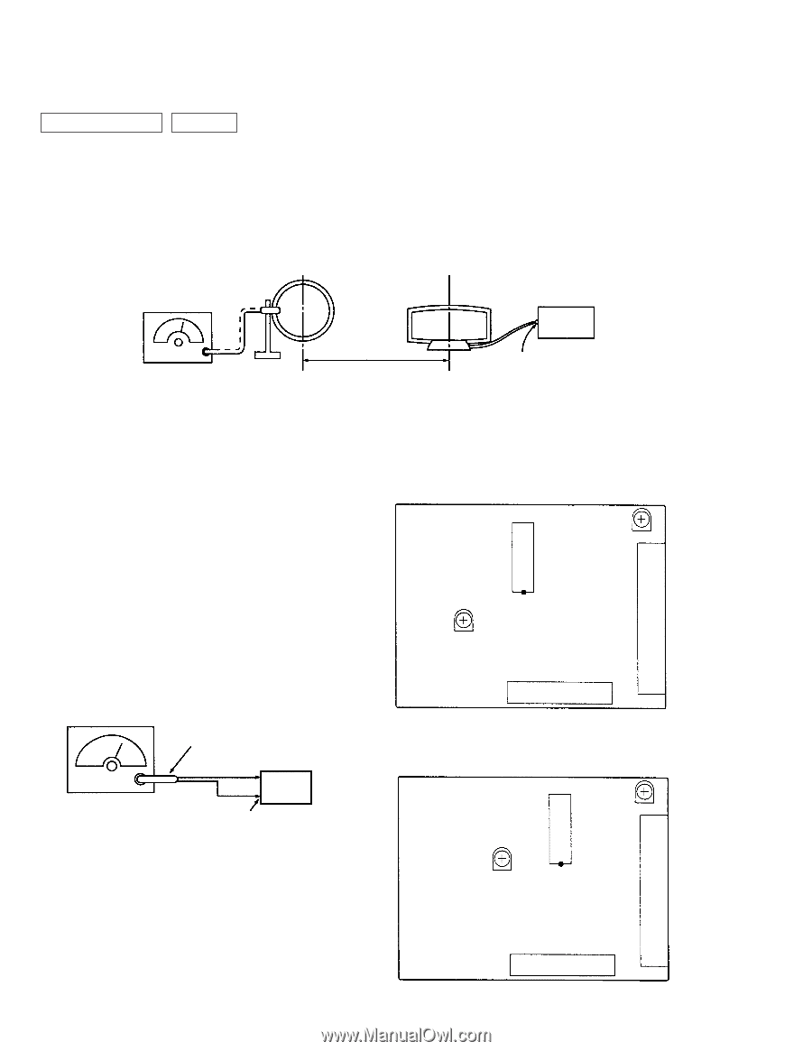
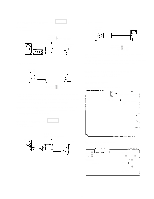
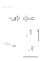
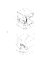
TUNER SECTION 0dB=1µV Note : As a front-end (FE1) is difficult to repair if faulty, replace it with new one. AM Tuned Level Adjustment Note : FM Tuned Level adjustment should be performed after this AM Tuned Level adjustment. Setting : Band : AM or MW loop antenna AM RF SSG • Abbreviation G : German model IT : Italian model loop antenna (Supplied accessories) 30% amplitude modulation by 400 Hz signal Carrier frequency : 999kHz (at 9kHz step) 1050kHz (at 10 kHz step) 60 cm AM antenna terminal (TM1) Field strength dB (µV/m)=SGG output level dB (µV/m)-26dB. Procedure : 1. Set the output of SGG so that the input level of the set becomes 55 dB. 2. Tune the set to 999 kHz or 1050 kHz . 3. Adjust RV41 (AEP, UK, IT, G models), RV42 (other models) to the point (moment) when the TUNED indicator will change from going off to going on. Adjustment Location AEP, UK, G, IT model [TCB BOARD] (Component Side) IC41 RV41 AM Tuned Level Adjustment Location : TCB board FM Tuned Level Adjustment RV42 Note : This adjustment should be performed after the AM Tuned FM Tuned Level Level Adjustement. TM1 Setting : Band : FM FM RF stereo signal generator 75Ω coaxial set Carrier frequency : 98MHz Modulation : AUDIO 1kHz, 75kHz deviation (100%) Output level : 25dB (at 75Ω open) FM ANTENNA terminal (TM1) (75Ω) Procedure : 1. Supply a 25dB 98 MHz signal from the ANTENNA terminal. 2. Tune the set to 98 MHz. 3. Adjust RV42 (AEP, UK, IT, G models), RV41 (other models) to the point (moment) when the TUNED indicator will change from going off to going on. Adjustment Location : TCB board FE1 Other model [TCB BOARD] (Component Side) IC2 RV41 FM Tuned Level RV42 AM Tuned Level TM1 FE1 - 14 -
-
 1
1 -
2
-
3
-
4
-
5
-
6
-
7
-
8
-
 9
9 -
 10
10 -
 11
11 -
 12
12 -
 13
13 -
 14
14 -
 15
15 -
 16
16 -
 17
17 -
 18
18 -
 19
19 -
20
-
21
-
22
-
23
-
24
-
25
-
26
-
27
-
28
-
29
-
30
-
31
-
32
-
33
-
34
-
35
-
36
-
37
-
38
-
39
-
40
-
41
-
42
-
43
-
44
-
45
-
46
-
47
-
48
-
49
-
50
-
51
-
52
-
53
-
54
-
55
-
56
-
57
-
58
-
59
-
60
-
61
-
62
-
63
-
64
-
65
-
66
-
67
-
68
-
69
-
70
-
71
-
72
-
73
-
74
-
75
-
76
-
77
-
78
 |
 |