Sony HCD-D670AV Service Manual - Page 5

Electrical Parts List, Exploded Views

Page 5 highlights

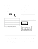
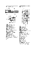
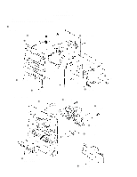
TABLE OF CONTEMTS Section Title Page SECTION 1. GENERAL 6 SECTION 2. DISASSEMBLY 2-1. Front Panel Assy and Main Board 8 2-2. TC Mechanism Deck 8 2-3. CD Mechanism Deck 9 2-4. BU Bracket Assy 9 2-5. Disc Table 10 SECTION 3. MECHANICAL ADJUSTMENTS ......... 11 SECTION 4. ELECTRICAL ADJUSTMENTS DECK Section 11 TUNER Section 14 CD Section 15 SECTION 5. DIAGRAMS 5-1. Circuit boards location 17 5-2. IC Pin Functions 18 • IC501 Graphic Control (ASD0204 18 • IC701 Master Control (TMP87CS64YF 19 5-3. Block Diagrams • Main Section 22 • Tuner Section (US, CND, E, AUS, MX, PX, AR Model 25 • Tuner Section (AEP, UK, G, IT Model 27 • DECK Section 29 • CD Section 31 5-4. Schematic Diagram - Tuner Section - (US, CND, E, AUS, MX, PX, AR Model 34 5-5. Printed Wiring Board - Tuner Section - (US, CND, E, AUS, MX, PX, AR Model 36 5-6. Schematic Diagram - Tuner Section - (AEP, UK, G, IT Model 38 5-7. Printed Wiring Board - Tuner Section - (AEP, UK, G, IT Model 40 5-8. Schematic Diagram - CD Panel Section 41 5-9. Printed Wiring Board - CD Panel Section 42 5-10. Schematic Diagram - CD Section 45 5-11. Printed Wiring Board - CD Section 47 5-12. Printed Wiring Board - Deck Section 49 5-13. Schematic Diagram - Deck Section 51 5-14. Printed Wiring Board - Main Section 57 5-15. Schematic Diagram - Main Section 59 5-16. Schematic Diagram - Panel Section 64 5-17. Printed Wiring Board - Panel Section 69 5-18. Printed Wiring Board - Power Section 73 5-19. Schematic Diagram - Power Section 77 5-20. Schematic Diagram - CD Motor Section 80 5-21. Printed Wiring Board - CD Motor Section 81 5-22. IC Block Diagrams - CD Section 83 Section Title Page SECTION 6. EXPLODED VIEWS 6-1. Case and Back Panel Section 85 6-2. Panel Board Section 86 6-3. Front panel Section 87 6-4. Chassis Section 88 6-5. TC Mechanism Section 1 (TCM-220WR2E 89 6-6. TC Mechanism Section 2 (TCM-220WR2E 90 6-7. TC Mechanism Section 3 (TCM-220WR2E 91 6-8. CD Mechanism Section(CDM37-5BD19 92 6-9. Base Unit Section (BU-5BD19 93 SECTION 7. ELECTRICAL PARTS LIST 94 • Abbreviation G : German model IT : Italian model MX : Mexican model AUS : Australian model AR : Argentine model - 5 -

  • 1
  • 2
  • 3
  • 4
  • 5
  • 6
  • 7
  • 8
  • 9
  • 10
  • 11
  • 12
  • 13
  • 14
  • 15
  • 16
  • 17
  • 18
  • 19
  • 20
  • 21
  • 22
  • 23
  • 24
  • 25
  • 26
  • 27
  • 28
  • 29
  • 30
  • 31
  • 32
  • 33
  • 34
  • 35
  • 36
  • 37
  • 38
  • 39
  • 40
  • 41
  • 42
  • 43
  • 44
  • 45
  • 46
  • 47
  • 48
  • 49
  • 50
  • 51
  • 52
  • 53
  • 54
  • 55
  • 56
  • 57
  • 58
  • 59
  • 60
  • 61
  • 62
  • 63
  • 64
  • 65
  • 66
  • 67
  • 68
  • 69
  • 70
  • 71
  • 72
  • 73
  • 74
  • 75
  • 76
  • 77
  • 78

— 5 —
TABLE OF CONTEMTS
Section
T
itle
P
a
g
e
SECTION 1. GENERAL
......................................................
6
SECTION 2. DISASSEMBLY
2-1. Front Panel Assy and Main Board
.........................................
8
2-2. TC Mechanism Deck
.............................................................
8
2-3. CD Mechanism Deck
.............................................................
9
2-4. BU Bracket Assy
....................................................................
9
2-5. Disc Table
............................................................................
10
SECTION 3. MECHANICAL ADJUSTMENTS
.........
11
SECTION 4. ELECTRICAL ADJUSTMENTS
DECK Section
.............................................................................
11
TUNER Section
...........................................................................
14
CD Section
...................................................................................
15
SECTION 5. DIAGRAMS
5-1. Circuit
boards location
........................................................
17
5-2. IC Pin Functions
..................................................................
18
• IC501 Graphic Control (ASD0204)
..................................
18
• IC701 Master Control (TMP87CS64YF)
..........................
19
5-3. Block Diagrams
• Main Section
......................................................................
22
• Tuner Section
(US, CND, E, AUS, MX, PX, AR Model)
.........................
25
• Tuner Section
(AEP, UK, G, IT Model)
....................................................
27
• DECK Section
...................................................................
29
• CD Section
.........................................................................
31
5-4. Schematic Diagram — Tuner Section —
(US, CND, E, AUS, MX, PX, AR Model)
...........................
34
5-5. Printed Wiring Board — Tuner Section —
(US, CND, E, AUS, MX, PX, AR Model)
...........................
36
5-6. Schematic Diagram — Tuner Section —
(AEP, UK, G, IT
Model)
.....................................................
38
5-7. Printed Wiring Board — Tuner Section —
(AEP, UK, G, IT
Model)
.....................................................
40
5-8. Schematic Diagram — CD Panel Section —
......................
41
5-9. Printed Wiring Board — CD Panel Section —
....................
42
5-10. Schematic Diagram — CD Section —
..............................
45
5-11. Printed Wiring Board — CD Section —
............................
47
5-12. Printed Wiring Board — Deck Section —
.........................
49
5-13. Schematic Diagram — Deck Section —
............................
51
5-14. Printed Wiring Board — Main Section —
.........................
57
5-15. Schematic Diagram — Main Section —
............................
59
5-16. Schematic Diagram — Panel Section —
...........................
64
5-17. Printed Wiring Board — Panel Section —
........................
69
5-18. Printed Wiring Board — Power Section —
.......................
73
5-19. Schematic Diagram — Power Section —
..........................
77
5-20. Schematic Diagram — CD Motor Section —
...................
80
5-21. Printed Wiring Board — CD Motor Section —
.................
81
5-22. IC Block Diagrams — CD Section —
...............................
83
Section
T
itle
P
a
g
e
SECTION 6. EXPLODED VIEWS
6-1. Case and Back Panel Section
...............................................
85
6-2. Panel Board Section
.............................................................
86
6-3. Front panel Section
..............................................................
87
6-4. Chassis Section
....................................................................
88
6-5. TC Mechanism Section 1 (TCM-220WR2E)
......................
89
6-6. TC Mechanism Section 2 (TCM-220WR2E)
......................
90
6-7. TC Mechanism Section 3 (TCM-220WR2E)
......................
91
6-8. CD Mechanism Section(CDM37-5BD19)
...........................
92
6-9. Base Unit Section (BU-5BD19)
...........................................
93
SECTION 7. ELECTRICAL PARTS LIST
...................
94
• Abbreviation
G
: German model
IT
: Italian model
MX
: Mexican model
AUS: Australian model
AR
: Argentine model