Sony HCD-D670AV Service Manual - Page 3
MODEL IDENTIFICATION, BACK PANEL, Notes on chip component replacement
 |
View all Sony HCD-D670AV manuals
Add to My Manuals
Save this manual to your list of manuals |
Page 3 highlights
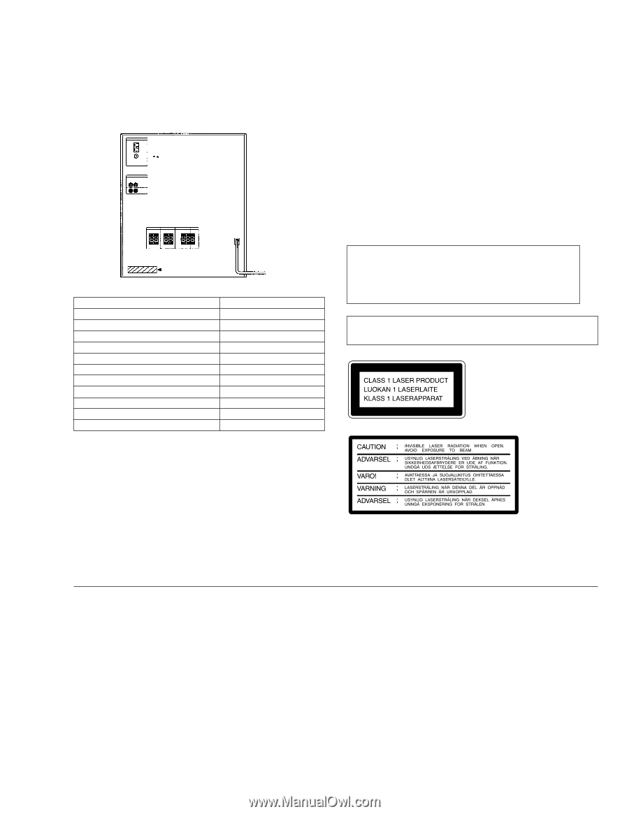
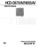
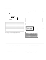
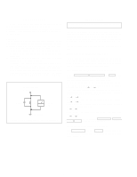
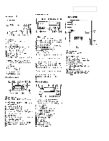
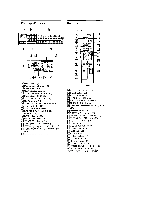
MODEL IDENTIFICATION - BACK PANEL - Parts No. MODEL D670AV: US model D670AV: Canadian model N555AV: AEP model N555AV: German model N555AV: Italian model N555AV: UK model N555AV: E model N555AV: Argentine model N555AV: Australian model N555AV: PX model N555AV: Mexican model PARTS No. 4-978-193-0π 4-978-193-1π 4-978-193-2π 4-978-193-3π 4-978-193-4π 4-978-193-5π 4-978-194-0π 4-978-194-1π 4-978-194-2π 4-978-194-3π 4-978-194-4π NOTE: The AEP model has lndonsian and Malaysia products. The contents of both products are completely the same. Notes on chip component replacement • Never reuse a disconnected chip component. • Notice that the minus side of a tantalum capacitor may be damaged by heat. Flexible Circuit Board Repairing • Keep the temperature of soldering iron around 270˚C during repairing. • Do not touch the soldering iron on the same conductor of the circuit board (within 3 times). • Be careful not to apply force on the conductor when soldering or unsoldering. CAUTION Use of controls or adjustments or performance of procedures other than those specified herein may result in hazardous radiation exposure. Laser component in this product is capable of emitting radiation exceeding the limit for Class 1. This appliance is classified as a CLASS 1 LASER product. The CLASS 1 LASER PRODUCT MARKING is located on the rear exterior. This caution label is located inside the unit. SAFETY-RELATED COMPONENT WARNING !! COMPONENTS IDENTIFIED BY MARK ! OR DOTTED LINE WITH MARK ! ON THE SCHEMATIC DIAGRAMS AND IN THE PARTS LIST ARE CRITICAL TO SAFE OPERATION. REPLACE THESE COMPONENTS WITH SONY PARTS WHOSE PART NUMBERS APPEAR AS SHOWN IN THIS MANUAL OR IN SUPPLEMENTS PUBLISHED BY SONY. ATTENTION AU COMPOSANT AYANT RAPPORT À LA SÉCURITÉ!! LES COMPOSANTS IDENTIFIÉS PAR UNE MARQUE ! SUR LES DIAGRAMMES SCHÉMATIQUES ET LA LISTE DES PIÈCES SONT CRITIQUES POUR LA SÉCURITÉ DE FONCTIONNEMENT. NE REMPLACER CES COMPOSANTS QUE PAR DES PIÈCES SONY DONT LES NUMÉROS SONT DONNÉS DANS CE MANUEL OU DANS LES SUPPLÉMENTS PUBLIÉS PAR SONY. - 3 -
-
 1
1 -
 2
2 -
 3
3 -
 4
4 -
 5
5 -
 6
6 -
 7
7 -
 8
8 -
 9
9 -
10
-
11
-
12
-
13
-
14
-
15
-
16
-
17
-
18
-
19
-
20
-
21
-
22
-
23
-
24
-
25
-
26
-
27
-
28
-
29
-
30
-
31
-
32
-
33
-
34
-
35
-
36
-
37
-
38
-
39
-
40
-
41
-
42
-
43
-
44
-
45
-
46
-
47
-
48
-
49
-
50
-
51
-
52
-
53
-
54
-
55
-
56
-
57
-
58
-
59
-
60
-
61
-
62
-
63
-
64
-
65
-
66
-
67
-
68
-
69
-
70
-
71
-
72
-
73
-
74
-
75
-
76
-
77
-
78
 |
 |