Sony HDWM2000/20 Operation Manual - Page 14
Audio control MIXING mixing setting mode button
 |
View all Sony HDWM2000/20 manuals
Add to My Manuals
Save this manual to your list of manuals |
Page 14 highlights
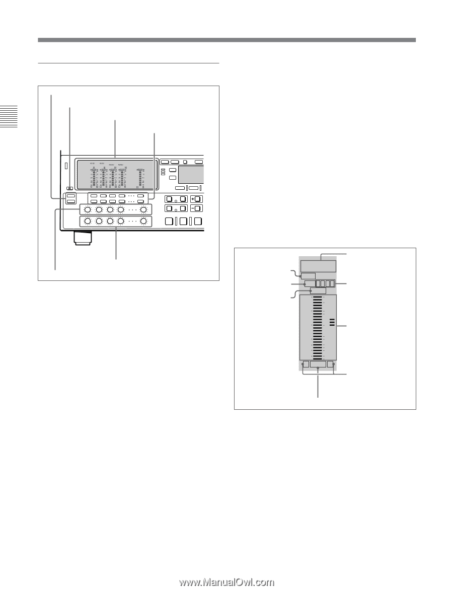
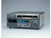
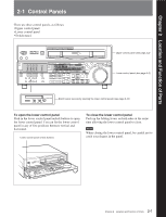
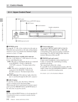
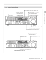
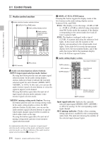
2-1 Control Panels Chapter 2 Location and Function of Parts 1 Audio control section 1 Audio selection function selector buttons 2 DISPLAY FULL/FINE button 3 Audio setting display section 4 Audio monitor signal selection buttons 5 REC controls 6 PB controls 1 Audio selection function selector buttons INPUT (input signal selection mode) button: Pressing this button puts the unit into input signal selection mode. In the audio setting display section, indicators flash to indicate the currently selected signal for each channel (HDSDI, SDTI, AES/EBU, or ANA). In this state, you can use the audio monitor signal selection buttons to select the signal to input to each channel. Pressing this button again takes the unit out of input signal selection mode and puts it into monitor signal selection mode. MIXING (mixing setting mode) button: Pressing this button puts the unit into mixing setting mode. In the audio setting display section, the MIX indicator flashes. In this state, you can use the audio monitor signal selection buttons to specify which input channel signal will be recorded on which audio track on the tape. Pressing this button again takes the unit out of mixing setting mode and puts it into monitor signal selection mode. For information about how to operate in input signal selection mode, mixing setting mode, and monitor signal selection mode, see the descriptions of the audio monitor signal selection buttons 4 on page 2-5. 2 DISPLAY FULL/FINE button Pressing this button toggles the display mode of the level meters in the audio setting display section between FULL and FINE. FULL: The display covers the range -60 dB to 0 dB or -40 dB to +20 dB as selected using setup menu item 806. In this mode the segment of the display corresponding to the current audio level and all lower segments light. FINE: The display is enlarged, with a step of 0.25 dB. A segment indicating the reference level lights. In this mode only the segment of the display corresponding to the current audio level lights. If the audio level exceeds the maximum display level, the top segment flashes, and if the audio level goes below the minimum display level, the bottom segment flashes. 3 Audio setting display section Input signal indicator DATA indicator MIX indicator OVER indicator HDSDI SDTI AES/EBU/ANA DATA 5 6 7 8 MIX 1 2 3 4 dB OVER dB 0 20 2 -10 110 Input channel indicator -20 0 -1 -30 -10 -40 -20 -2 -60 -40 L EMPH R Level meter Monitor channel L and R indicators EMPH indicator Input signal indicator: Indicates the currently selected input signal (HDSDI, SDTI, AES/EBU, or ANA for analog) for the corresponding audio input channel. MIX (mixing) indicator: Flashes when a mixing setting operation is enabled for the corresponding audio track. The indicator showing the number of the selected input channel lights. 2-4 Chapter 2 Location and Function of Parts
-
 1
1 -
2
-
3
-
4
-
5
-
6
-
7
-
8
-
 9
9 -
 10
10 -
 11
11 -
 12
12 -
 13
13 -
 14
14 -
 15
15 -
 16
16 -
 17
17 -
 18
18 -
 19
19 -
20
-
21
-
22
-
23
-
24
-
25
-
26
-
27
-
28
-
29
-
30
-
31
-
32
-
33
-
34
-
35
-
36
-
37
-
38
-
39
-
40
-
41
-
42
-
43
-
44
-
45
-
46
-
47
-
48
-
49
-
50
-
51
-
52
-
53
-
54
-
55
-
56
-
57
-
58
-
59
-
60
-
61
-
62
-
63
-
64
-
65
-
66
-
67
-
68
-
69
-
70
-
71
-
72
-
73
-
74
-
75
-
76
-
77
-
78
-
79
-
80
-
81
-
82
-
83
-
84
-
85
-
86
-
87
-
88
-
89
-
90
-
91
-
92
-
93
-
94
-
95
-
96
-
97
-
98
-
99
-
100
-
101
-
102
-
103
-
104
-
105
-
106
-
107
-
108
-
109
-
110
-
111
-
112
-
113
-
114
-
115
-
116
-
117
-
118
-
119
-
120
-
121
-
122
-
123
-
124
-
125
-
126
-
127
-
128
-
129
-
130
-
131
-
132
-
133
-
134
-
135
-
136
-
137
-
138
-
139
-
140
-
141
-
142
-
143
-
144
-
145
-
146
-
147
-
148
-
149
-
150
-
151
-
152
-
153
-
154
-
155
-
156
 |
 |