Sony HDWM2000/20 Operation Manual - Page 22
Editing control ALARM indicator and KEY INHI, indicator, PLAYER button and RECORDER, button
 |
View all Sony HDWM2000/20 manuals
Add to My Manuals
Save this manual to your list of manuals |
Page 22 highlights
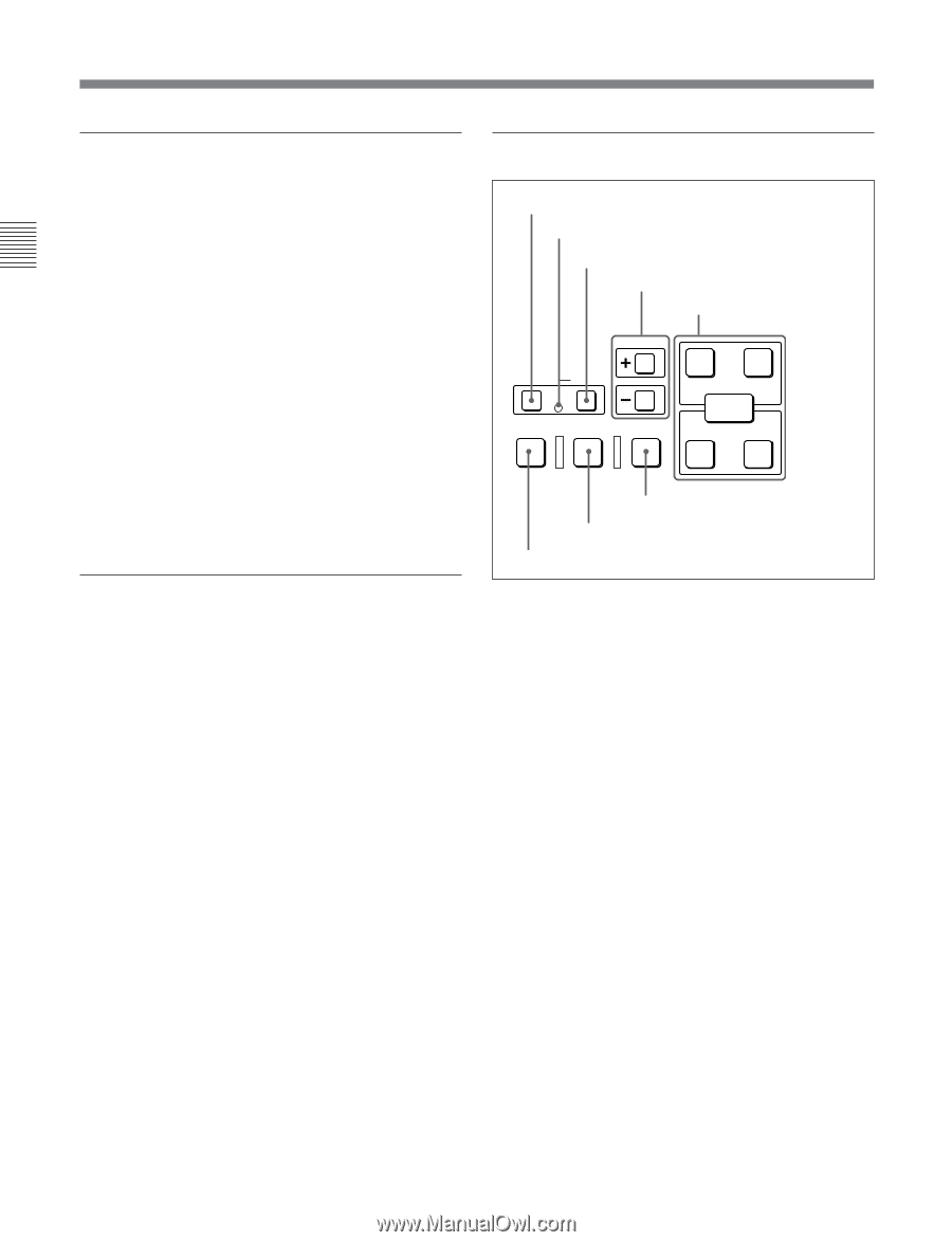
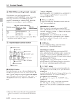
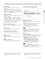
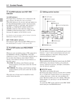
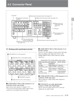
Chapter 2 Location and Function of Parts 2-1 Control Panels qa ALARM indicator and KEY INHI indicator ALARM indicator This lights when a hardware error is detected on the unit, and goes off when the error is resolved. When this indicator is lit, an error message appears in the time data/menu display section. If you are using the HDSDI OUTPUT 3 (SUPER), SDI OUTPUT 3 (SUPER) or COMPOSITE VIDEO OUTPUT 3 (SUPER) connector, then when the setting of F4 (CHARA) in function menu page 4 is ON, the error message also appears on the monitor screen. For details on error messages, refer to Section 1-24 in the Maintenance Manual Volume 1. KEY INHI (inhibit) indicator This indicator lights when the KEY INHI switch on the switch panel (see page 2-14) is set to ON. qs PLAYER button and RECORDER button When you carry out editing using a VTR connected to the REMOTE 1-IN(9P) or REMOTE 1-OUT(9P) connector (see page 2-18) as the player and this unit as the recorder, these buttons select which VTR the editing control buttons and tape transport buttons on this unit control. PLAYER: The editing control buttons and tape transport buttons on this unit control the external player VTR. RECORDER: The editing control buttons and tape transport buttons on this unit control the recorder (this unit). When this unit is being used in standalone mode, neither button functions. qd Editing control section 1 DMC EDIT button 2 MEMORY indicator 3 DELETE button 4 TRIM buttons 5 Edit point setting buttons TRIM DMC EDIT DELETE MEMORY IN AUDIO OUT ENTRY PREVIEW AUTO EDIT REVIEW IN OUT 6 REVIEW button 7 AUTO EDIT button 8 PREVIEW button 1 DMC EDIT button Use this button to memorize the playback speed varied between -1 and +2 times normal speed, and carry out automatic playback or automatic editing using the memorized playback speed. 2 MEMORY indicator When memorizing the playback speed using the DMC EDIT button, this indicator flashes as the playback speed is captured to memory, and lights continuously once the speed is captured. 3 DELETE button This deletes an existing edit point. Hold down this button and press the IN, OUT, AUDIO IN, or AUDIO OUT button which is lit, indicating an existing edit point, to delete the corresponding edit point. The button either goes off or flashes. When the button flashes, it is necessary to set the deleted edit point again. To cancel the DMC mode, hold down the DMC EDIT button and press the DELETE button. 2-12 Chapter 2 Location and Function of Parts
-
 1
1 -
2
-
3
-
4
-
5
-
6
-
7
-
8
-
9
-
10
-
11
-
12
-
13
-
14
-
15
-
16
-
 17
17 -
 18
18 -
 19
19 -
 20
20 -
 21
21 -
 22
22 -
 23
23 -
 24
24 -
 25
25 -
 26
26 -
 27
27 -
28
-
29
-
30
-
31
-
32
-
33
-
34
-
35
-
36
-
37
-
38
-
39
-
40
-
41
-
42
-
43
-
44
-
45
-
46
-
47
-
48
-
49
-
50
-
51
-
52
-
53
-
54
-
55
-
56
-
57
-
58
-
59
-
60
-
61
-
62
-
63
-
64
-
65
-
66
-
67
-
68
-
69
-
70
-
71
-
72
-
73
-
74
-
75
-
76
-
77
-
78
-
79
-
80
-
81
-
82
-
83
-
84
-
85
-
86
-
87
-
88
-
89
-
90
-
91
-
92
-
93
-
94
-
95
-
96
-
97
-
98
-
99
-
100
-
101
-
102
-
103
-
104
-
105
-
106
-
107
-
108
-
109
-
110
-
111
-
112
-
113
-
114
-
115
-
116
-
117
-
118
-
119
-
120
-
121
-
122
-
123
-
124
-
125
-
126
-
127
-
128
-
129
-
130
-
131
-
132
-
133
-
134
-
135
-
136
-
137
-
138
-
139
-
140
-
141
-
142
-
143
-
144
-
145
-
146
-
147
-
148
-
149
-
150
-
151
-
152
-
153
-
154
-
155
-
156
 |
 |