Sony HDWM2000/20 Operation Manual - Page 141
Error Message List, Message, Description
 |
View all Sony HDWM2000/20 manuals
Add to My Manuals
Save this manual to your list of manuals |
Page 141 highlights
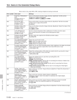
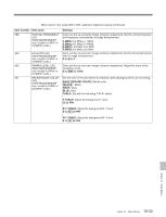
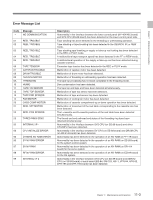
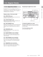
Chapter 11 Maintenance and Inspection Error Message List Code Message - NO COMMUNICATION 01 REEL TROUBLE 02 REEL TROUBLE 03 REEL TROUBLE 04 REEL TROUBLE 05 REEL TROUBLE 06 TAPE TENSION 07 CAPSTAN TROUBLE 08 DRUM TROUBLE 09 TH/UNTH MOTOR 0A THREADING 10 HUMID 11 TAPE T/E SENSOR 12 TAPE TOP SENSOR 13 TAPE END SENSOR 14 FAN MOTOR 20 CASS COMP MOTOR 21 REEL SFT MOTOR 22 REEL POS SENSOR 23 THRED RING SENS 92 INTERNAL I/F1 93 CPU INITIALIZE ERROR 95 OTHERS NV-RAM ERROR 96 SY NV-RAM ERROR 97 SV NV-RAM 98 RF NV-RAM ERROR 99 INTERNAL I/F 2 Description Abnormality in the interface between the lower control panel (KY-464/465 board) and SYS CPU (SS-89 board) has been detected on the lower control panel side. Tape slacking has been detected in the threading or unthreading operation. Tape slacking or tape breaking has been detected in the SEARCH, FF,or REW mode. Tape slacking,tape breaking,or supply or take-up reel locking has been detected in the REC or PLAY mode. A malfunctional tape transport speed has been detected in the FF or REW mode. A malfunctional operation of the supply or take-up reel has been detected during cassette insertion. Excessive tape tension has been detected in the REC or PLAY mode. Malfunction of capstan motor has been detected. Malfunction of drum motor has been detected. Malfunction of threading or unthreading operation has been detected. The tape top processing has not been completed in the threading mode. Dew condensation has been detected. The tape top and tape end have been detected simultaneously. Malfunction of tape top sensor has been detected. Malfunction of tape end sensor has been detected. Malfunction of cooling fan motor has been detected. Malfunction of cassette compartment-up or down operation has been detected. Malfunction of movement of the reel table corresponding to the cassette size has been detected. The L-cassette and S-cassette positions of the reel table have been detected simultaneously. The thread end and unthread end states of the threading ring have been detected simultaneously. Abnormality in the interface between SYS CPU (on SS-89 board) and other CPU/MPU has been detected. Abnormality in the interface between SV CPU (on SS-89 board) and DRUM CPU (on DR-414 board) has been detected. Abnormality has been detected in the operation of an NV-RAM on FP-119 board. Abnormality has been detected in the operation of an NV-RAM (on SS-89 board) for the system control system. Abnormality has been detected in the operation of an NV-RAM (on DR-414 board) for the servo system. Abnormality has been detected in the operation of an NV-RAM (on EQ-84 board) for the RF system. Abnormality in the interface between SYS CPU (on SS-89 board) and SERVO CPU (on SS-89 board) or each board (EQ-84, DM-123, HIF-1, VPR-64, APR-52, DPR-195 and DPR-155 board) has been detected. 11-3 Chapter 11 Maintenance and Inspection
-
 1
1 -
2
-
3
-
4
-
5
-
6
-
7
-
8
-
9
-
10
-
11
-
12
-
13
-
14
-
15
-
16
-
17
-
18
-
19
-
20
-
21
-
22
-
23
-
24
-
25
-
26
-
27
-
28
-
29
-
30
-
31
-
32
-
33
-
34
-
35
-
36
-
37
-
38
-
39
-
40
-
41
-
42
-
43
-
44
-
45
-
46
-
47
-
48
-
49
-
50
-
51
-
52
-
53
-
54
-
55
-
56
-
57
-
58
-
59
-
60
-
61
-
62
-
63
-
64
-
65
-
66
-
67
-
68
-
69
-
70
-
71
-
72
-
73
-
74
-
75
-
76
-
77
-
78
-
79
-
80
-
81
-
82
-
83
-
84
-
85
-
86
-
87
-
88
-
89
-
90
-
91
-
92
-
93
-
94
-
95
-
96
-
97
-
98
-
99
-
100
-
101
-
102
-
103
-
104
-
105
-
106
-
107
-
108
-
109
-
110
-
111
-
112
-
113
-
114
-
115
-
116
-
117
-
118
-
119
-
120
-
121
-
122
-
123
-
124
-
125
-
126
-
127
-
128
-
129
-
130
-
131
-
132
-
133
-
134
-
135
-
 136
136 -
 137
137 -
 138
138 -
 139
139 -
 140
140 -
 141
141 -
 142
142 -
 143
143 -
 144
144 -
 145
145 -
 146
146 -
147
-
148
-
149
-
150
-
151
-
152
-
153
-
154
-
155
-
156
 |
 |