Sony HSCU300RF Operation Manual - Page 10
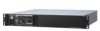
HKCU-FP2 CCU Control Panel (Optional), MASTER GAIN controls
 |
View all Sony HSCU300RF manuals
Add to My Manuals
Save this manual to your list of manuals |
Page 10 highlights
HKCU-FP2 CCU Control Panel (Optional) The switches and knobs not described below are identical to those on the front panel. See "Front Panel" (page 7). a b cd e f g Optional panel controls hi j k l m a PANEL ACTIVE button Activates the optional HKCU-FP2 CCU Control Panel to control the camera connected to the CCU (panel active state). When the button is lit, the IRIS/MB ACTIVE indicator also turns on simultaneously. When the button is not lit, the optional panel is deactivated (lock state) to prevent inadvertent operation. b SW1, SW2 (assignable switch 1, 2) buttons Controls the function assigned to each button on the page in the CCU CONFIGURATION menu. The button light turns on/off as the assigned function is switched on/off. See "ASSIGNABLE/CUSTOM" on page 26 on "". c BARS (color bars) button Switches on the color bar signal output to the monitor connected to the CCU (button light turns on). Pressing the button again restores the previous signal output. d STANDARD button Stores the current camera settings as the reference file data values in the camera (button light turns on for a few seconds). While the button is lit, pressing the button again cancels the operation and restores the previous data values. e SHUTTER controls Controls the shutter settings. ON button ECS (extended clear scan) button Display UP/DOWN lever • ON button Switches the normal shutter function on/off (button light turns on/off). • ECS (extended clear scan) button Switches the extended clear scan function on/off (button light turns on/off). • Display When the ECS button is lit: Displays the clear scan frequency. When the ON button is lit: Displays the shutter speed. • UP/DOWN lever When the ECS button is lit: Adjusts the clear scan frequency. UP increases the frequency, and DOWN decreases the frequency. When the ON button is lit: Adjusts the shutter speed. UP increases the shutter speed, and DOWN decreases the shutter speed. Holding the lever UP or DOWN advances the setting in that direction. f MASTER GAIN controls Controls the video output signal gain in response to the lighting of the subject. Display UP/DOWN lever • Display Displays the video output signal gain setting (dB units). • UP/DOWN lever Adjusts the video output signal gain setting (dB units). UP increases the gain, and DOWN decreases the gain. Holding the lever UP or DOWN advances the setting in that direction. g ALARM indicator Lights up red to indicate an error in the CCU or camera system. h CALL button Sends a call signal to the camera connected to the CCU and any external controller (such as the MSU-1000/1500 Master Setup Unit or RCP-1000-series Remote Control Panel). The CALL button is commonly used to raise the camera operator or external control equipment operators on the intercom. 10 Locations and Functions of Parts
-
 1
1 -
2
-
3
-
4
-
 5
5 -
 6
6 -
 7
7 -
 8
8 -
 9
9 -
 10
10 -
 11
11 -
 12
12 -
 13
13 -
 14
14 -
 15
15 -
16
-
17
-
18
-
19
-
20
-
21
-
22
-
23
-
24
-
25
-
26
-
27
-
28
-
29
-
30
-
31
-
32
-
33
-
34
 |
 |
