Sony HSCU300RF Operation Manual - Page 5
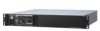
System Configuration Example (HSCU300RF, Optical Digital Transmission), HSCU300RF, Camera Control Unit
 |
View all Sony HSCU300RF manuals
Add to My Manuals
Save this manual to your list of manuals |
Page 5 highlights
System Configuration Example (HSCU300RF, Optical Digital Transmission) Microphone HDVF-200/C35W Viewfinder HDVF-550/C550W/C730W Viewfinder Picture Monitor Waveform Monitor CAC-12 Microphone Holder Zoom Lens (for ENG/EFP) VCT-14 Tripod Adaptor Tripod for portable camera HSC300RF HSC100RF HD Color Camera VF attachment shoe b) Intercom headset Return video input Sync input Prompter video input BNC BNC Video router Optical fiber cable USB drive Power supply for a script light HSCU300RF Camera Control Unit Video output HD-SDI/SD-SDI/VBS AC power to router/ switcher LAN cable CAC-6 Return Video Selector (mounts on front panel) HKCU-FP2 Front Control Panel CCA-5 cable Hub LAN cable AC power LAN cable a) HDVF-550/C550W/C730W Viewfinder MSU-1000/1500 Master Setup Unit RCP-1000-series Remote Control Panel VF attachment shoe b) Camera hangers c) HSC300RF HD Color Camera Optical fiber cable HSCU300RF Camera Control Unit Zoom Lens (for studio use) HDLA1500-series Large Lens Adaptor AC power CCA-5 cable Power supply for a script light General-purpose power supply DC 12 V (Max. 5 A) d) BKP-7911 Script Holder RCP-1000-series Remote Control Panel a) Supported only when using the multi-camera option b) Supplied with the HDVF-550/C550W/C730W, Part No.: A-7612-405-E c) Supplied with the HDLA1500/1505, Part No.: A-1128-405-A d) For general-purpose DC 12 V output, the serial number must be the following or higher : HDLA1500: 13001 or 43001, HDLA1503: 52001, HDLA1505: 11001, 41001 or 401001, HDLA1507: 401001 5 Overview
-
 1
1 -
 2
2 -
 3
3 -
 4
4 -
 5
5 -
 6
6 -
 7
7 -
 8
8 -
 9
9 -
 10
10 -
 11
11 -
12
-
13
-
14
-
15
-
16
-
17
-
18
-
19
-
20
-
21
-
22
-
23
-
24
-
25
-
26
-
27
-
28
-
29
-
30
-
31
-
32
-
33
-
34
 |
 |
