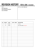
Sony KLV32S400A Revision History - Page 4
SAFETY NOTES, Caution Handling of LCD Panel, Safety Check-Out, Leakage Test, WARNING !, 4. WARNING - manual
 |
UPC - 011110668585
View all Sony KLV32S400A manuals
Add to My Manuals
Save this manual to your list of manuals |
Page 4 highlights
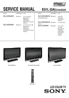
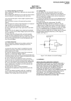
KLV-26,32,32/H/S,37 S400A RM-GA011 SECTION 1 SAFETY NOTES 1-1. Caution Handling of LCD Panel When installing the LCD Panel, make sure you are grounded with a wrist band. When installing the LCD Panel on the wall, the panel must be secured using the 4 mounting holes on the rear cover. 1) Do not press the panel or frame edge to avoid the risk of electric shock. 2) Do not scratch or press on the panel with any sharp objects. 3) Do not leave the module in high temperature or in areas of high humidity for an extended period of time. 4) Do not expose the LCD panel to direct sunlight. 5) Avoid contact with water. It may cause short circuit within the module. 6) Disconnect the AC adapter when replacing the backlight (CCFL) or inverter circuit. (High voltage occurs at the inverter circuit at 650Vrms) 7) Always clean the LCD panel with a soft cloth material. 8) Use care when handling the wires or connectors of the inverter circuit. Damaging the wires may cause a short circuit. 9) Protect the panel from ESD to avoid damaging the electronic circuit (C-MOS). 1-3. Leakage Test The AC leakage from any exposed metal part to earth ground and from all exposed metal parts to any exposed metal part having a return to chassis must not exceed 0.5mA (500 microamperes). Leakage current can be measured by any one of the three methods:1. A commercial leakage tester such as the SIMPSON 229 or RCA WT-540A. Follow the manufacturers instructions to use those instructions. 2. A battery-operated AC milliampmeter. The DATA PRECISION 245 digital multimeter is suitable for this job. 3. Measuring the voltage drop across a resistor by means of a VOM or battery operated AC voltmeter. The 'limit' indication is 0.75V so analog meters must have an accurate low voltage scale. The SIMPSON'S 250 and SANWA SH-63TRD are examples of passive VOMs that are suitable. Nearly all battery operated digital multimeters that have a 2 VAC range are suitable. (see Figure 1.) To Exposed Metal Parts on Set 1-2. Safety Check-Out After correcting the original service problem, perform the following safety checks before releasing the set to the customer:- 0.15 µF 1.5 kΩ AC Voltmeter (0.75 V) 1) Check the area of your repair for unsoldered or poorly soldered connections. Check the entire board surface for solder splashes and bridges. 2) Check the interboard wiring to ensure that no wires are "pinched" or contact high-wattage resistors. 3)Check all control knobs, shields, covers, ground straps and mounting hardware have been replaced. Be absolutely certain you have replaced all the insulators. 4) Look for unauthorized replacement parts, particularly transistors that were installed during a previous repair. Point them out to the customer and recommend their replacement. 5) Look for parts which, though functioning show obvious signs of deterioration. Point them out to the customer and recommend their replacement. 6) Check the line cords for cracks and abrasion. Recommend the replacement of any such line cord to the customer. 7) Check the antenna terminals, metal trim, "metallized" knobs, screws and all other exposed metal parts for AC leakage. Check leakage test as described next. Earth Ground Figure 1. AC voltmeter to check AC leakage 1-4. WARNING ! SAFETY-RELATED COMPONENT WARNING! COMPONENTS IDENTIFIED BY SHADING AND MARK ! ON THE EXPLODED VIEWS ARE CRITICAL FOR SAFE OPERATION. REPLACE THESE COMPONENTS WITH SONY PARTS WHOSE PART NUMBERS APPEAR AS SHOWN IN THIS MANUAL OR IN SUPPLEMENTS PUBLISHED BY SONY. CIRCUIT ADJUSTMENTS THAT ARE CRITICAL FOR SAFE OPERATION ARE IDENTIFIED IN THIS MANUAL. FOLLOW THESE PROCEDURES WHENEVER CRITICAL COMPONENTS ARE REPLACED OR IMPROPER OPERATION IS SUSPECTED. - 3 -
-
 1
1 -
 2
2 -
 3
3 -
 4
4 -
 5
5 -
 6
6 -
 7
7 -
 8
8 -
 9
9 -
 10
10 -
11
-
12
-
13
-
14
-
15
-
16
-
17
-
18
-
19
-
20
-
21
-
22
-
23
-
24
-
25
-
26
-
27
-
28
-
29
-
30
-
31
-
32
-
33
-
34
-
35
-
36
-
37
-
38
-
39
-
40
-
41
-
42
-
43
-
44
-
45
-
46
-
47
-
48
-
49
-
50
-
51
-
52
-
53
-
54
-
55
-
56
-
57
-
58
-
59
-
60
-
61
-
62
-
63
-
64
-
65
-
66
-
67
-
68
-
69
-
70
-
71
-
72
-
73
-
74
-
75
-
76
-
77
-
78
-
79
-
80
-
81
 |
 |
