Sony KLV32S400A Revision History - Page 6
SELF DIAGNOSTIC FUNCTION, Overview of Control Buttons, LED Display Specification, LED Display Control - 32
 |
UPC - 011110668585
View all Sony KLV32S400A manuals
Add to My Manuals
Save this manual to your list of manuals |
Page 6 highlights
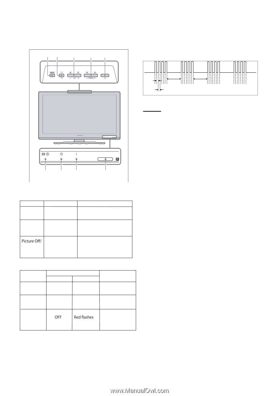
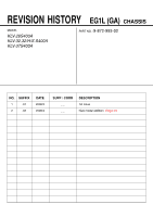
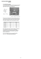
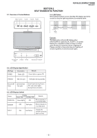
KLV-26,32,32/H/S,37 S400A RM-GA011 SECTION 2 SELF DIAGNOSTIC FUNCTION 2-1. Overview of Control Buttons MENU TV/VIDEO VOLUME CHANNEL POWER 2-4. LED Pattern When safety shutdown occurs, Standby LED display reports the cause by using the lightning patterns as indicated below. 0.3 sec 2.0 sec 0.3 sec 2.0 sec Example: The figure above shows LED display when SHUTDOWN is caused by DC_ALERT 2. It repeats flashing for a specified number of times in 0.3sec/ cycle and has a 2 seconds interval of lighting off. Please note that a 2 seconds interval of lighting off is fixed regardless of abnormal state types. PICTURE OFF/ STANDBY POWER TIMER REMOTE/LIGHT SENSOR 2-2. LED Display Specification LED Type Description Remark POWER Green: LED Green lights at power ON. STANDBY Red: One LED Red lights during standby. Timer Green/Amber : Two LEDs Green lights during Picture OFF and amber lights during Timer activation. 2-3. LED Display Control Status POWER ON Display Power LED Standby LED Green lights OFF Remark Microcomputer is in a normal state. STANDBY OFF Red lights Microcomputer is in a sleep state. Failure Classify the trouble causes by the no. of red. - 5 -
-
 1
1 -
 2
2 -
 3
3 -
 4
4 -
 5
5 -
 6
6 -
 7
7 -
 8
8 -
 9
9 -
 10
10 -
 11
11 -
 12
12 -
13
-
14
-
15
-
16
-
17
-
18
-
19
-
20
-
21
-
22
-
23
-
24
-
25
-
26
-
27
-
28
-
29
-
30
-
31
-
32
-
33
-
34
-
35
-
36
-
37
-
38
-
39
-
40
-
41
-
42
-
43
-
44
-
45
-
46
-
47
-
48
-
49
-
50
-
51
-
52
-
53
-
54
-
55
-
56
-
57
-
58
-
59
-
60
-
61
-
62
-
63
-
64
-
65
-
66
-
67
-
68
-
69
-
70
-
71
-
72
-
73
-
74
-
75
-
76
-
77
-
78
-
79
-
80
-
81
 |
 |