Sony MZ-R900 Service Manual - Page 10
Holder, 11. Motor, Flexible, Board
 |
View all Sony MZ-R900 manuals
Add to My Manuals
Save this manual to your list of manuals |
Page 10 highlights
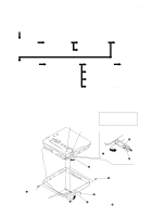
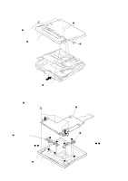
MZ-R900 3-10. HOLDER ASSY 5 Remove the holder assy in the direction of arrow D. 1 Open the holder assy. A D B 2 Push the convex portion toward the direction B and open the holder assy toward the direction A to erect uprightly. 3 Remove the concave portion C in the direction of arrow C. 3-11. MOTOR FLEXIBLE BOARD 1 Remove four solders of "motor, DC (sled) (M602)". 2 adhesive sheet Note: Align a circular hole in the stripping paper with a circular hole in the "motor, DC (sled)", when mounting the motor flexible board. 4 boss 1 Remove two solders of DC motor (over write head up/down) (M603). 1 Remove four solders of "motor, DC (spindle) (M601)". 3 motor flexible board DC motor (sled) circular hole 10
-
 1
1 -
2
-
3
-
4
-
 5
5 -
 6
6 -
 7
7 -
 8
8 -
 9
9 -
 10
10 -
 11
11 -
 12
12 -
 13
13 -
 14
14 -
 15
15 -
16
-
17
-
18
-
19
-
20
-
21
-
22
-
23
-
24
-
25
-
26
-
27
-
28
-
29
-
30
-
31
-
32
-
33
-
34
-
35
-
36
-
37
-
38
-
39
-
40
-
41
-
42
-
43
-
44
-
45
-
46
-
47
-
48
-
49
-
50
 |
 |

10
MZ-R900
3-10. HOLDER
ASSY
3-11. MOTOR
FLEXIBLE
BOARD
2
Push the convex portion
toward the direction
B
and
open the holder assy toward
the direction
A
to erect uprightly.
3
Remove the concave portion
in the direction of arrow
C
.
5
Remove the holder assy in the
direction of arrow
D
.
D
C
B
A
1
Open the holder assy.
4
boss
1
Remove four solders of
“motor, DC (sled) (M602)”.
1
Remove four solders of
“motor, DC (spindle) (M601)”.
3
motor flexible board
DC motor (sled)
circular hole
1
Remove two solders of
DC motor (over write head up/down) (M603).
2
adhesive sheet
Note:
Align a circular hole in the
stripping paper with a circular hole
in the “motor, DC (sled)”,
when mounting the motor
flexible board.