Sony MZ-R900 Service Manual - Page 6
Panel, Upper, Module, Panel, Upper
 |
View all Sony MZ-R900 manuals
Add to My Manuals
Save this manual to your list of manuals |
Page 6 highlights
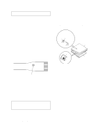
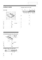
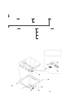
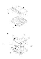
MZ-R900 3-3. PANEL ASSY, UPPER SECTION 3 two screws (1.4) 4 panel assy, upper section 1 flexible board (CN801) 3 two screws (1.4) 2 Push button (open). 3-4. "LCD MODULE", "PANEL ASSY, UPPER" 1 four screws (1.7) 2 LCD module 3 button (A), control Note: On installation, adjust the hole of "button (A), control" and boss of "panel assy, upper". (in the fig. a , b ) a d b c 4 button (B), control Note: On installation, adjust the boss of "button (B), control" and hole of "panel assy, upper". (in the fig. c , d ) a b d 5 panel assy, upper c 6
-
 1
1 -
 2
2 -
 3
3 -
 4
4 -
 5
5 -
 6
6 -
 7
7 -
 8
8 -
 9
9 -
 10
10 -
 11
11 -
 12
12 -
13
-
14
-
15
-
16
-
17
-
18
-
19
-
20
-
21
-
22
-
23
-
24
-
25
-
26
-
27
-
28
-
29
-
30
-
31
-
32
-
33
-
34
-
35
-
36
-
37
-
38
-
39
-
40
-
41
-
42
-
43
-
44
-
45
-
46
-
47
-
48
-
49
-
50
 |
 |

6
MZ-R900
3-3.
PANEL
ASSY,
UPPER
SECTION
3-4.
“LCD
MODULE”,
“PANEL
ASSY,
UPPER”
3
two screws
(1.4)
4
panel assy, upper section
2
Push button (open).
3
two screws
(1.4)
1
flexible board
(CN801)
1
four screws (1.7)
3
button (A), control
Note:
On installation,
adjust the hole of
“button (A), control”
and boss of “panel assy,
upper”. (in the fig.
,
)
4
button (B), control
Note:
On installation,
adjust the boss of
“button (B), control” and
hole of “panel assy, upper”.
(in the fig.
,
)
5
panel assy, upper
2
LCD module
a
b
a
a
b
b
c
c
d
d
d
c