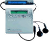
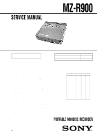
Sony MZ-R900 Service Manual - Page 5
Mz-r900, Disassembly - mz r900s
 |
View all Sony MZ-R900 manuals
Add to My Manuals
Save this manual to your list of manuals |
Page 5 highlights
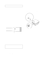
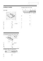
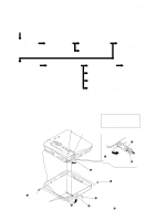
• This set can be disassembled in the order shown below. 3-1. DISASSEMBLY FLOW SET SECTION 3 DISASSEMBLY MZ-R900 3-2. PANEL ASSY, BOTTOM 3-3. PANEL ASSY, UPPER SECTION 3-5. MAIN BOARD ASSY 3-4. "LCD MODULE", "PANEL ASSY, UPPER" 3-6. "CASE ASSY, BATTERY", "MAIN BOARD" 3-7. STRIP, ORNAMENTAL 3-8. "MD MECHANISM DECK (MT-MZR900-171)", "CHASSIS ASSY, SET" 3-9. SERVICE ASSY, OP (LCX-4R) 3-11. MOTOR FLEXIBLE BOARD 3-10. HOLDER ASSY 3-12. MOTOR, DC (SLED) (M602) 3-13. "MOTOR, DC (SPINDLE) (M601)", "MOTOR, DC (OVER WRITE HEAD UP/DOWN) (M603)" Note: Follow the disassembly procedure in the numerical order given. 3-2. PANEL ASSY, BOTTOM S801 S802 Note: On installation, adjust the position of both two switches (S801, S802) and two knobs (hold). 3 lid, battery case 5 two screws (1.4) knob (hold) 1 Open the lid, battery case. 4 Close the battery terminal (plus). 2 claw 5 two screws (1.4) 5 screw (1.4) A 6 Remove the "panel assy, bottom" in the direction of arrow A. 5
-
 1
1 -
 2
2 -
 3
3 -
 4
4 -
 5
5 -
 6
6 -
 7
7 -
 8
8 -
 9
9 -
 10
10 -
 11
11 -
12
-
13
-
14
-
15
-
16
-
17
-
18
-
19
-
20
-
21
-
22
-
23
-
24
-
25
-
26
-
27
-
28
-
29
-
30
-
31
-
32
-
33
-
34
-
35
-
36
-
37
-
38
-
39
-
40
-
41
-
42
-
43
-
44
-
45
-
46
-
47
-
48
-
49
-
50
 |
 |
