Sony PCV-RZ22G System Reference Manual - Page 67
Power Supply and Aux Power Headers
 |
View all Sony PCV-RZ22G manuals
Add to My Manuals
Save this manual to your list of manuals |
Page 67 highlights
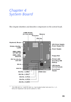
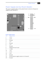
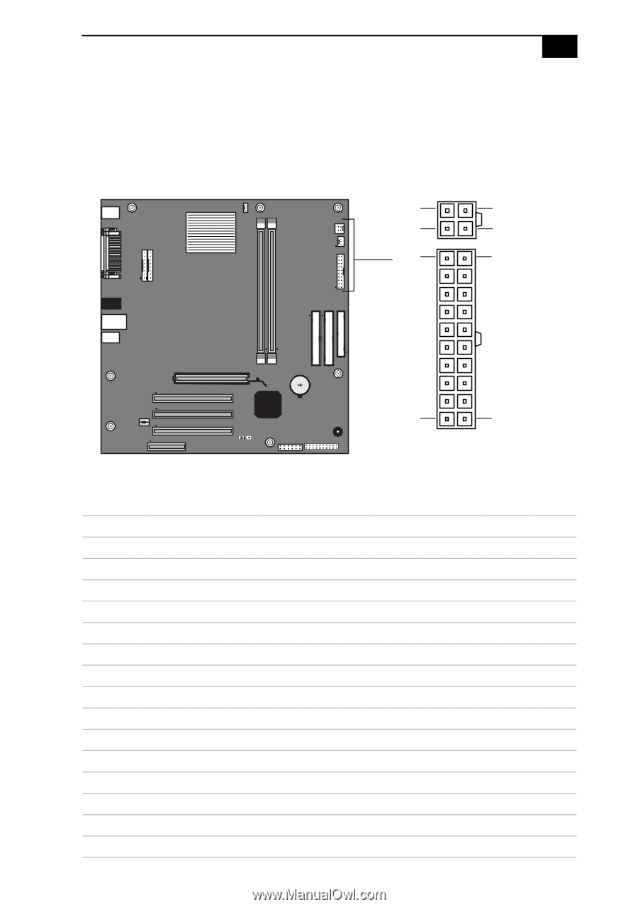
System Board 53 Power Supply and Aux Power Headers The power supply header on the system board connects to the power supply header labelled P1. 2 4 1 3 10 20 1 11 Power Supply header Pin Signal Name 1 +3.3 V 2 +3.3 V 3 Ground 4 +5 V 5 Ground 6 +5 V 7 Ground 8 PWRGD (Power Good) 9 +5 VSB 10 +12 V 11 +3.3 V 12 -12 V 13 Ground 14 PS-ON# (power supply remote on/off control) 15 Ground
-
 1
1 -
2
-
3
-
4
-
5
-
6
-
7
-
8
-
9
-
10
-
11
-
12
-
13
-
14
-
15
-
16
-
17
-
18
-
19
-
20
-
21
-
22
-
23
-
24
-
25
-
26
-
27
-
28
-
29
-
30
-
31
-
32
-
33
-
34
-
35
-
36
-
37
-
38
-
39
-
40
-
41
-
42
-
43
-
44
-
45
-
46
-
47
-
48
-
49
-
50
-
51
-
52
-
53
-
54
-
55
-
56
-
57
-
58
-
59
-
60
-
61
-
 62
62 -
 63
63 -
 64
64 -
 65
65 -
 66
66 -
 67
67 -
 68
68 -
 69
69 -
 70
70 -
 71
71 -
 72
72 -
73
-
74
-
75
-
76
-
77
-
78
-
79
-
80
-
81
-
82
-
83
-
84
-
85
-
86
-
87
-
88
-
89
-
90
-
91
-
92
-
93
-
94
-
95
-
96
-
97
-
98
-
99
-
100
 |
 |
System Board
53
Power Supply and Aux Power Headers
The power supply header on the system board connects to the power
supply header labelled P1.
Power Supply header
Pin
Signal Name
1
+3.3 V
2
+3.3 V
3
Ground
4
+5 V
5
Ground
6
+5 V
7
Ground
8
PWRGD (Power Good)
9
+5 VSB
10
+12 V
11
+3.3 V
12
-12 V
13
Ground
14
PS-ON# (power supply remote on/off control)
15
Ground
10
1
11
20
1
2
3
4