Sony PDWF800 User Manual (PDW-700 / PDW-F800 Operation Manual for Firmware Ver - Page 28
Left side and upper AUDIO IN CH-1/CH-2/CH-3/CH-4
 |
View all Sony PDWF800 manuals
Add to My Manuals
Save this manual to your list of manuals |
Page 28 highlights
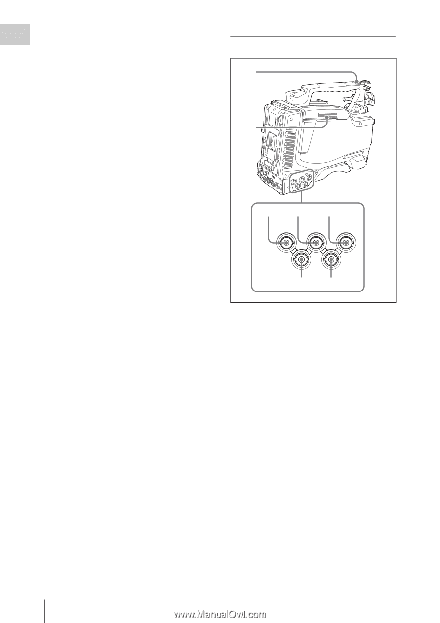
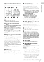
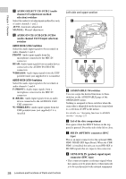
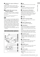
Chapter 1 Overview k AUDIO SELECT CH-1/CH-2 (audio channel 1/2 adjustment method selection) switches Select the audio level adjustment method for each of audio channels 1 and 2. AUTO: Automatic adjustment MANUAL: Manual adjustment l AUDIO IN CH-1/CH-2/CH-3/CH-4 (audio channel 1/2/3/4 input selection) switches AUDIO IN CH-1/CH-2 switches Select the audio input signals to be recorded on audio channels 1 and 2. FRONT: Audio input signals from the microphone connected to the MIC IN connector REAR: Audio input signals from an audio device connected to the AUDIO IN CH1/CH2 connectors WIRELESS: Audio input signals from the UHF portable tuner (not supplied) if it is installed AUDIO IN CH-3/CH-4 switches Select the audio input signals to be recorded on audio channels 3 and 4. F (FRONT): Audio input signals from a microphone connected to the MIC IN connector R (REAR): Audio input signals from an audio device connected to the AUDIO IN CH1/ CH2 connectors W (WIRELESS): Audio input signals from the UHF portable tuner (not supplied) if it is installed 28 Locations and Functions of Parts and Controls Left side and upper section 1 2 345 SDI IN (OPTION) GENLOCK IN TC IN TEST TC OUT OUT 67 a ASSIGNABLE 3/4 switches You can assign the desired functions to these switches on the ASSIGNABLE page of the OPERATION menu. Nothing is assigned to these switches when the camcorder is shipped from the factory (equivalent to a selection of OFF in the menu). For details, see "Assigning functions to ASSIGN switches" on page 221. b Lid of the disc compartment This opens when the EJECT button on the top panel is pressed. Press the side of the lid to close. c SDI IN (OPTION) connector (BNC type) This is an input connector for the optional CBKHD01 HD/SD SDI Input Board. When the CBKHD01 is installed, the unit can record HD-SDI or SD-SDI signals that are input to this connector. d GENLOCK IN (genlock signal input) connector (BNC type) • This connector inputs a reference signal when the camera is to be genlocked or when timecode is to be synchronized with external equipment.
-
 1
1 -
2
-
3
-
4
-
5
-
6
-
7
-
8
-
9
-
10
-
11
-
12
-
13
-
14
-
15
-
16
-
17
-
18
-
19
-
20
-
21
-
22
-
 23
23 -
 24
24 -
 25
25 -
 26
26 -
 27
27 -
 28
28 -
 29
29 -
 30
30 -
 31
31 -
 32
32 -
 33
33 -
34
-
35
-
36
-
37
-
38
-
39
-
40
-
41
-
42
-
43
-
44
-
45
-
46
-
47
-
48
-
49
-
50
-
51
-
52
-
53
-
54
-
55
-
56
-
57
-
58
-
59
-
60
-
61
-
62
-
63
-
64
-
65
-
66
-
67
-
68
-
69
-
70
-
71
-
72
-
73
-
74
-
75
-
76
-
77
-
78
-
79
-
80
-
81
-
82
-
83
-
84
-
85
-
86
-
87
-
88
-
89
-
90
-
91
-
92
-
93
-
94
-
95
-
96
-
97
-
98
-
99
-
100
-
101
-
102
-
103
-
104
-
105
-
106
-
107
-
108
-
109
-
110
-
111
-
112
-
113
-
114
-
115
-
116
-
117
-
118
-
119
-
120
-
121
-
122
-
123
-
124
-
125
-
126
-
127
-
128
-
129
-
130
-
131
-
132
-
133
-
134
-
135
-
136
-
137
-
138
-
139
-
140
-
141
-
142
-
143
-
144
-
145
-
146
-
147
-
148
-
149
-
150
-
151
-
152
-
153
-
154
-
155
-
156
-
157
-
158
-
159
-
160
-
161
-
162
-
163
-
164
-
165
-
166
-
167
-
168
-
169
-
170
-
171
-
172
-
173
-
174
-
175
-
176
-
177
-
178
-
179
-
180
-
181
-
182
-
183
-
184
-
185
-
186
-
187
-
188
-
189
-
190
-
191
-
192
-
193
-
194
-
195
-
196
-
197
-
198
-
199
-
200
-
201
-
202
-
203
-
204
-
205
-
206
-
207
-
208
-
209
-
210
-
211
-
212
-
213
-
214
-
215
-
216
-
217
-
218
-
219
-
220
-
221
-
222
-
223
-
224
-
225
-
226
-
227
-
228
-
229
-
230
-
231
-
232
-
233
-
234
-
235
-
236
-
237
-
238
-
239
-
240
-
241
-
242
-
243
-
244
-
245
-
246
-
247
-
248
-
249
-
250
-
251
-
252
-
253
-
254
-
255
-
256
-
257
-
258
-
259
-
260
-
261
-
262
-
263
-
264
-
265
-
266
-
267
-
268
-
269
-
270
-
271
-
272
-
273
-
274
-
275
-
276
-
277
-
278
-
279
-
280
-
281
-
282
-
283
-
284
-
285
-
286
-
287
-
288
-
289
-
290
-
291
-
292
-
293
-
294
-
295
 |
 |