Sony PVM-2030/BS Operating Instructions - Page 15
Specifications
 |
View all Sony PVM-2030/BS manuals
Add to My Manuals
Save this manual to your list of manuals |
Page 15 highlights
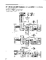
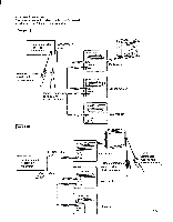
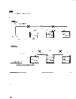
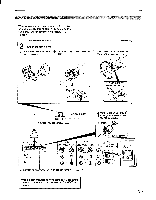
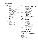
CONNECTING A MICFIOVIVIIVTER When you connect a microcomputer to this monitor, attach the supplied ferrite core. If you do not do this, this monitor will not conform to mandatory FCC standards. 2 Attach the ferrite core. CD, Set the cord inside the ferrite C core (supplied). Close the lid tightly until the clamps click. © Loop a plastic binder (supplied) at the far end of the core. ti Clamps Pull it tight to prevent the core from moving. Ferrite core (supplied) Microcomputer Shielded RGB cable (not supplied) 1Connect the shielded RGB cable (not supplied) to the CMPTR connector. C) Insert. Q Tighten the screws. CMPTR OFF ON SYN REEN tot oo=o 0,:.i o.;43009 © IN CONTROL S © OUT LINE A IN OFFIll] ON OUT LINE IN OFF CID ON OUT VTR IN E S VINOD r TR (Vi 0 (0 OOP I VIDEO 6, AUDIO I 6 R VIDEO AUDIO 0 RI O L SPEAKER (USE 8-16Q1 C±) AUDIO R For signal to be connected, see "SPECIFICATIONS" on page 17. AC OUT 12()V 50i6GHz 100W MAX loj Whena microcomputerhas onlya composite video output connector, connect it to the LINE A or LINE B VIDEO IN connector. 15
-
 1
1 -
2
-
3
-
4
-
5
-
6
-
7
-
8
-
9
-
 10
10 -
 11
11 -
 12
12 -
 13
13 -
 14
14 -
 15
15 -
 16
16 -
 17
17 -
 18
18
 |
 |
