Sony PVM-2030/BS Operating Instructions - Page 7
Connectors
 |
View all Sony PVM-2030/BS manuals
Add to My Manuals
Save this manual to your list of manuals |
Page 7 highlights
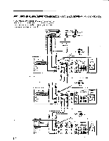
Connectors M SYNC ON GREEN select switch 02 CMPTR (computer) connector (25-pin, D-sub) El CONTROL S connectors _ CONTRO, S 4 1- I LINE NLINE B 75-ohm termination switch VIDEO IN connector (BNC type) VIDEO OUT connector (BNC type) AUDIO UR IN jacks (phono jack) AUDIO UR OUT jacks (phono jack) M SYNC ON GREEN select switch When an RGB input source is connected to CMPTR connector, set this switch to: ON to synchronize with the sync signal on G-signal. OFF to synchronize with H.N. sync signal or composite sync signal. CMPTR (computer) connector (25-pin, D-sub) Connect to a microcomputor with digital or analog RGB outputs. For the pin assignment, refer to SPECIFICATIONS. CONTROL S INIOUT connectors Connect to the CONTROL S connectors of a VTR or several monitors. It is then possible to control the system with a single Remote Commander. M LINE AILINE B VIDEO IN connector (BNC type) AUDIO UR IN jacks (phono jack) Connect to the video and audio outputs of a VTR or a camera. VIDEO OUT connector (BNC type) AUDIO UR OUT jacks (phono jack) Loop-through outputs of the IN connector and jacks. Connect to the video and audio inputs of another monitor. 75-ohm termination switchWhen only the VIDEO IN connector is used (nothing is connected to the VIDEO OUT connector), set this switch to ON. When both connectors are used together for a loopthrough connection), set this switch to OFF.
-
 1
1 -
 2
2 -
 3
3 -
 4
4 -
 5
5 -
 6
6 -
 7
7 -
 8
8 -
 9
9 -
 10
10 -
 11
11 -
 12
12 -
13
-
14
-
15
-
16
-
17
-
18
 |
 |
