Sony UPDR80 Operating Instructions - Page 4
Features, Location and Function of, Parts and Controls - up dr80 printer
 |
View all Sony UPDR80 manuals
Add to My Manuals
Save this manual to your list of manuals |
Page 4 highlights
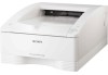
Introduction Introduction Features The UP-DR80 Digital Photo Printer is a dye sublimation thermal transfer printer providing high quality and high resolution printing of computer image data in full color (256 gradations process and 16.7 million colors). Location and Function of Parts and Controls Front System Configuration Computer Controls the printer operations. USB cable UP-DR80 Digital Photo Printer A 1 ON/STANDBY switch/indicator When this switch is pressed, the indicator lights, and the printer enters the ready state. When it is pressed again, the indicator flashes and then goes out, and the printer enters the standby state. B Paper cover Printouts stack here. The margins of empty space that are created between each printout are cut off during printing and dropped into the scrap receptacle at the back of the paper cover. Scrap receptacle 4 Features / Location and Function of Parts and Controls C Paper outlet Printouts are ejected here. D Vent openings E Media tray (page 9) The ink ribbon and paper are loaded here. F Stopper (page 13) Flip this stopper up in order to prevent the ejected printouts from falling.
-
 1
1 -
 2
2 -
 3
3 -
 4
4 -
 5
5 -
 6
6 -
 7
7 -
 8
8 -
 9
9 -
 10
10 -
11
-
12
-
13
-
14
-
15
-
16
-
17
-
18
-
19
-
20
-
21
-
22
-
23
-
24
 |
 |
