Sony VPL VW10HT Operating Instructions - Page 9
Location and Function of, Controls - lamp cover
 |
UPC - 027242565180
View all Sony VPL VW10HT manuals
Add to My Manuals
Save this manual to your list of manuals |
Page 9 highlights
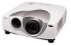
Location and Function of Controls Front/Left Side 3 21 8 45 7 6 Rear/Right Side/Bottom 09 qa qs qd qf Location and Function of Controls 1 Zoom ring Adjusts the size of the picture. 2 Focus ring Adjusts the picture focus. 3 Ventilation holes (exhaust) 4 Lens Remove the lens cap before projection. 5 Front remote control detector (SIRCS receiver) 6 Adjusters When a picture is projected on the out of the screen, adjust the picture using these adjusters. For details on how to use the adjusters, see "How to use the adjuster" on page 10 (GB). 7 Connector panel For details, see page 12 (GB). 8 Control panel For details, see "Control panel" on page 11 (GB). 9 AC IN socket Connects the supplied AC power cord. 0 Rear remote control detector (SIRCS receiver) qa Lamp cover qs Rear adjusters qd Ventilation holes (intake)/air filter cover About ventilation holes Notes • Do not place anything near the ventilation holes as it may cause internal heat build-up. Do not put your hand near the ventilation holes, or you may be burned. • Clean the air filter every 300 hours to ensure optimal performance. For details, see "Cleaning the Air Filter" on page 35 (GB). qf Adjuster buttons 9 (GB)
-
 1
1 -
2
-
3
-
 4
4 -
 5
5 -
 6
6 -
 7
7 -
 8
8 -
 9
9 -
 10
10 -
 11
11 -
 12
12 -
 13
13 -
 14
14 -
15
-
16
-
17
-
18
-
19
-
20
-
21
-
22
-
23
-
24
-
25
-
26
-
27
-
28
-
29
-
30
-
31
-
32
-
33
-
34
-
35
-
36
-
37
-
38
-
39
-
40
-
41
-
42
-
43
-
44
-
45
-
46
-
47
-
48
-
49
-
50
-
51
-
52
-
53
-
54
-
55
-
56
-
57
-
58
-
59
-
60
-
61
-
62
-
63
-
64
-
65
-
66
-
67
-
68
-
69
-
70
-
71
-
72
-
73
-
74
-
75
-
76
-
77
-
78
-
79
-
80
-
81
-
82
-
83
-
84
-
85
-
86
-
87
-
88
-
89
-
90
-
91
-
92
-
93
-
94
-
95
-
96
-
97
-
98
-
99
-
100
-
101
-
102
-
103
-
104
-
105
-
106
-
107
-
108
-
109
-
110
-
111
-
112
-
113
-
114
-
115
-
116
-
117
-
118
-
119
-
120
-
121
-
122
-
123
-
124
 |
 |
