Stihl BG 45 Instruction Manual - Page 5
Main Parts
 |
View all Stihl BG 45 manuals
Add to My Manuals
Save this manual to your list of manuals |
Page 5 highlights
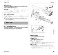
3 Main Parts WARNING Indicates a hazardous situation that, if not avoided, could result in death or serious injury. NOTICE Indicates a risk of property damage, including damage to the machine or its individual components. 2.2 Symbols in Text The following symbol is included to assist you with the use of the manual: Refers to a designated chapter or sub-chapter in this instruction manual. 3 Main Parts 3.1 Blower and Charger The blower is powered by an integrated lithium ion battery that cannot be removed from the power tool. 9 11 8 7 10 17 English 1 45 3 2 6 # 12 13 # 16 15 14 0000-GXX-2265-A1 0458-719-8621-A 1 Retaining Latch Locks/unlocks the trigger switch. 2 Trigger Switch Switches the motor on and off. 3 Trigger Switch Lockout Must be depressed while the retaining latch is unlocked to allow activation of the trigger switch. 4 Blower LEDs Indicate the blower's state of charge and display error messages regarding potential malfunctions in the power tool or its integrated battery. 3
-
 1
1 -
 2
2 -
 3
3 -
 4
4 -
 5
5 -
 6
6 -
 7
7 -
 8
8 -
 9
9 -
 10
10 -
 11
11 -
12
-
13
-
14
-
15
-
16
-
17
-
18
-
19
-
20
-
21
-
22
-
23
-
24
-
25
-
26
-
27
-
28
-
29
-
30
-
31
-
32
-
33
-
34
-
35
-
36
-
37
-
38
-
39
-
40
-
41
-
42
-
43
-
44
-
45
-
46
-
47
-
48
-
49
-
50
-
51
-
52
-
53
-
54
-
55
-
56
-
57
-
58
-
59
-
60
 |
 |
