Sub-Zero 427R Sub-Zero Design Guide - Page 48
Planning Information, PRO 48 Refrigeration
 |
View all Sub-Zero 427R manuals
Add to My Manuals
Save this manual to your list of manuals |
Page 48 highlights
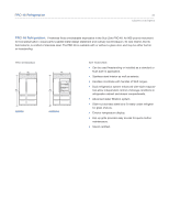
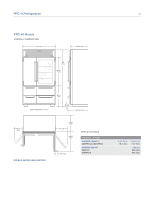
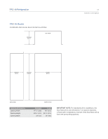
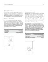
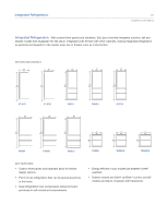
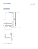
PRO 48 Refrigeration 48 Planning Information PRO 48 models can be used freestanding or installed as a standard or flush built-in application. For standard built-in installations, the face frame of the unit will extend 2" (51) beyond cabinetry. In flush built-in installations, the front of the face frame will be flush with surrounding cabinetry. ELECTRICAL REQUIREMENTS For PRO 48 models, the electrical supply should be located within the shaded area shown in the illustration below. Follow the National Electrical Code and local codes and ordinances when installing the receptacle. A separate circuit, servicing only this appliance, is required. A ground fault circuit interrupter (GFCI) is not recommended and may cause interruption of operation. Electrical Requirements Power Supply Circuit Breaker Receptacle 115 V AC, 60 Hz 15 amp 3-prong grounding-type FRONT VIEW 7" (178) E 6" (152) PLUMBING REQUIREMENTS PRO 48 models come with an automatic ice maker and a water filtration system. The water supply line should be located within the shaded area shown in the illustration below. The water supply line should be connected to the house supply with an easily accessible shut-off valve between the supply and the unit. Do not use self-piercing valves. A saddle valve kit is available through your authorized Sub-Zero dealer. The water line must not interfere with installation of the anti-tip bracket. IMPORTANT NOTE: A reverse osmosis system can be used provided there is constant water pressure of 35 psi (2.4 bar) to 120 psi (8.3 bar) supplied to the unit at all times. In this application, the water filtration system must be set to bypass mode. This is achieved by removing the water filter cartridge. Refer to the PRO 48 installation guide packed with the unit for detailed instructions. A copper line is not recommended for this application. Plumbing Requirements Water Supply Line 1/4" OD copper, braided stainless steel or PEX tubing Water Pressure 35-120 psi (2.4-8.3 bar) Excess Water Line for Connection 36" (914) 751/2" (1918) FROM FLOOR Location of electrical supply. 3" (76) 6" (152) 53/16" (132) FLOOR FRONT VIEW Location of water supply.
-
 1
1 -
2
-
3
-
4
-
5
-
6
-
7
-
8
-
9
-
10
-
11
-
12
-
13
-
14
-
15
-
16
-
17
-
18
-
19
-
20
-
21
-
22
-
23
-
24
-
25
-
26
-
27
-
28
-
29
-
30
-
31
-
32
-
33
-
34
-
35
-
36
-
37
-
38
-
39
-
40
-
41
-
42
-
 43
43 -
 44
44 -
 45
45 -
 46
46 -
 47
47 -
 48
48 -
 49
49 -
 50
50 -
 51
51 -
 52
52 -
 53
53 -
54
-
55
-
56
-
57
-
58
-
59
-
60
-
61
-
62
-
63
-
64
-
65
-
66
-
67
-
68
-
69
-
70
-
71
-
72
-
73
-
74
-
75
-
76
-
77
-
78
-
79
-
80
-
81
-
82
-
83
-
84
-
85
-
86
-
87
-
88
-
89
-
90
-
91
-
92
-
93
-
94
 |
 |
