Sub-Zero IC-30FI Integrated Installation Guide - Page 5
Electrical, Plumbing
 |
View all Sub-Zero IC-30FI manuals
Add to My Manuals
Save this manual to your list of manuals |
Page 5 highlights
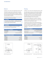
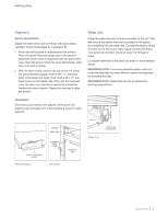
SITE PREPARATION Electrical Installation must comply with all applicable electrical codes. The electrical supply must be located within the shaded area shown in the illustration and chart below. A separate circuit, servicing only this appliance is required. A ground fault circuit interrupter (GFCI) is not recommended and may cause interruption of operation. The electrical outlet must be positioned with the grounding prong to the right of the thinner blades. CAUTION The outlet must be checked by a qualified electrician to be sure that it is wired with the correct polarity. Verify that the outlet is properly grounded. WARNING Do not use an extension cord, two-prong adapter or remove the power cord ground prong. ELECTRICAL REQUIREMENTS Power Supply Circuit Breaker Receptacle 115 VAC, 60 Hz 15 amp 3-prong grounding-type ELECTRICAL SUPPLY LOCATION WIDTH 18" Models 24" Models 27" Models 30" Models 36" Models A 6" (152) 91/2" (241) 11" (279) 121/2" (318) 151/2" (394) Plumbing Installation must comply with all applicable plumbing codes. The water supply line should be located within the shaded area shown in the illustrations below. The water supply line should be connected to the house supply with an easily accessible shut-off valve. Do not use self-piercing valves. The water supply line must be flush to the floor and not interfere with installation of the anti-tip bracket. Column and tall models with an ice maker or water dispenser feature a water filtration system. An in-line filter is required for drawer models with an ice maker when water conditions have a high sediment content. A reverse osmosis system can be used provided there is constant water pressure of 35-120 psi (2.4-8.3 bar) supplied to the unit at all times. In this application, the water filtration system must be bypassed. Refer to water filter bypass on page 15. A copper line is not recommended for this application. PLUMBING REQUIREMENTS Water Supply Line 1/4" OD copper, braided stainless steel or PEX tubing Water Pressure 35-120 psi (2.4-8.3 bar) Excess Water Line for Connection 36" (914) WATER SUPPLY LOCATION WIDTH 18" Models 24" Models 30" Models 36" Models A 3" (76) 51/2" (140) 6" (152) 9" (229) LEFT SIDE OF OPENING 41/2" (114) A FLOOR 1/4" (6) FRONT VIEW 41/4" (108) Electrical supply location. RIGHT SIDE OF OPENING A 3" (76) FLOOR 6" (152) FRONT VIEW A 1/2" BACK WALL (13) 6" (152) WATER LINE RIGHT SIDE OF OPENING TOP VIEW Water supply location (rear). Water supply location (bottom). subzero.com | 5
-
 1
1 -
 2
2 -
 3
3 -
 4
4 -
 5
5 -
 6
6 -
 7
7 -
 8
8 -
 9
9 -
 10
10 -
 11
11 -
12
-
13
-
14
-
15
-
16
-
17
-
18
-
19
-
20
-
21
-
22
-
23
-
24
-
25
-
26
-
27
-
28
-
29
-
30
-
31
-
32
-
33
-
34
-
35
-
36
-
37
-
38
-
39
-
40
-
41
-
42
-
43
-
44
 |
 |
