TEAC TA-1VP TA-1VP owners manual - Page 21
Left Cursor, Right Cursor, SETUP, Input Level Trim & Meter Input Select
 |
View all TEAC TA-1VP manuals
Add to My Manuals
Save this manual to your list of manuals |
Page 21 highlights
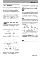
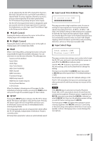
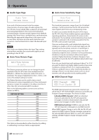
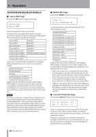
5 - Operation can be adjusted by the TA-1VP's Analog Trim function, the mixer channel trim (for a pre-fader insert effect), a channel fader (if using a separate channel as a return), or by an external preamp (if you have patched the TA‑1VP between the preamp and your mixer input). •• The TA-1VP's front panel level meter is designed to give you a quick overview of input signal level. For precise level adjustment, see the Input Level Trim & Meter Page in the Setup section below. ªª Ó (Left Cursor) Pressing this button will move the cursor to the left on display pages with multiple data fields. ªª Á (Right Cursor) Pressing this button will move the cursor to the right on display pages with multiple data fields. ªª PAGE When in the Setup Menu, pressing this button will cycle sequentially through the available edit pages. You can only move in one direction direction. The edit pages are: Input Level Trim & Meter Input Select Audio Type Auto-Tune Detune Auto-Tune Sensitivity MIDI Channel MIDI Controllers Footswitch Assign MIDI Dump (export) MIDI Receive enable (import) Factory Preset Restore LCD Contrast When the display is showing one of the pages for the individual processing modules, pressing the PAGE button will cycle through the available pages for that module. ªª SETUP Pressing the SETUP button will place the TA-1VP in Setup Mode. The button will light to indicate this state. Pressing the button again will exit Setup Mode and return you to whichever screen you were in immediately before entering Setup Mode. The Setup pages allow you to set parameters which affect the TA-1VP globally, independent of whichever Preset is currently active. All Setup Menu parameter values are automatically saved. ªª Input Level Trim & Meter Page In analog trim: 0dB This page provides a high resolution meter for ease in setting the input signal level. Turning the Data Knob adjusts the analog trim from -30 dB to +30 dB in 1 dB steps. (The default setting is 0 dB.) Analog trim is applied to both the line input and microphone inputs. Ideally, you should adjust the input to the highest level that does not consistently cause the meter to reach 0 dB. (Digital clipping, which introduces a particularly nasty-sounding distortion, will occur if the input exceeds 0 dB.) ªª Input Select Page Input select: LINE Phantom power: OFF This page contains two settings, one to select which input the TA-1VP uses, and one to turn the Phantom power on and off for the MIC IN microphone input. Use the Ó or Á buttons to move the cursor between the two settings, and use the Data Knob to change the setting. The input can be either the LINE IN input (rear panel) or MIC IN input (front panel XLR). (The default setting is LINE.) The Phantom power can be OFF (default setting) or ON The TA-1VP remembers the input trim and settings even when powered off, and these settings are not part of the presets. NOTE If the MIC IN input is selected, turning the Phantom Power ON or OFF can produce a burst of noise from the connected microphone. Phantom power is applied to the MIC IN connector even when the LINE IN is selected, so select LINE IN first, then turn the phantom power setting on and OFF before setting input to MIC IN. The front panel +48V LED lights when phantom power is being supplied to the MIC IN connector. Connecting or disconnecting a microphone while this is lit can cause speaker- and ear- damaging noise, or even damage the microphone. TASCAM TA-1VP 21
-
 1
1 -
2
-
3
-
4
-
5
-
6
-
7
-
8
-
9
-
10
-
11
-
12
-
13
-
14
-
15
-
 16
16 -
 17
17 -
 18
18 -
 19
19 -
 20
20 -
 21
21 -
 22
22 -
 23
23 -
 24
24 -
 25
25 -
 26
26 -
27
-
28
-
29
-
30
-
31
-
32
-
33
-
34
-
35
-
36
-
37
-
38
-
39
-
40
-
41
-
42
-
43
-
44
 |
 |
