TP-Link TD-8840T User Guide - Page 9
Hardware Installation - adsl2
 |
UPC - 845973060176
View all TP-Link TD-8840T manuals
Add to My Manuals
Save this manual to your list of manuals |
Page 9 highlights
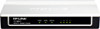
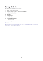
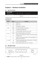
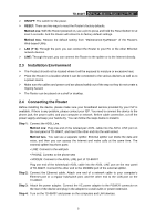
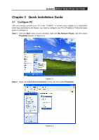
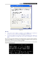
TD-8840T ADSL2+ Modem Router User Guide Chapter 2 Hardware Installation 2.1 The Front Panel Figure 2-1 The Router's LEDs are located on the front panel (View from left to right). For details, please refer to LED Explanation. LED Explanation: Name Status Indication Power On Power is on. Off Power is off. On The LINE port is linked up. ADSL Flash The ADSL negotiation is in progress. Off The LINE port is linked down. On A successful PPP connection has been built. Internet Flash Off Data is being transferred over the Internet. There is no successful PPP connection or the Router works on Bridge mode. There is a successful connection on the corresponding 1~4 On (LAN) port but no activity. 1~4 (LAN) There is no connection on the corresponding 1~4 (LAN) port Off or the connection is abnormal. Flash Data is being transferred over the 1~4 (LAN) port 2.2 The Back Panel The following parts are located on the rear panel (View from left to right). Figure 2-2 ¾ POWER: The Power socket is where the power adapter connects to. 4
-
 1
1 -
2
-
3
-
 4
4 -
 5
5 -
 6
6 -
 7
7 -
 8
8 -
 9
9 -
 10
10 -
 11
11 -
 12
12 -
 13
13 -
 14
14 -
15
-
16
-
17
-
18
-
19
-
20
-
21
-
22
-
23
-
24
-
25
-
26
-
27
-
28
-
29
-
30
-
31
-
32
-
33
-
34
-
35
-
36
-
37
-
38
-
39
-
40
-
41
-
42
-
43
-
44
-
45
-
46
-
47
-
48
-
49
-
50
-
51
-
52
-
53
-
54
-
55
 |
 |