TP-Link TL-SC4171G User Guide - Page 11
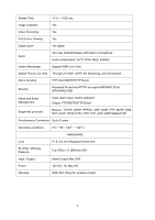
Rear view, Power Connector, Reset Button, Reset, Antenna Connector, Audio In, Audio Out
 |
UPC - 845973054045
View all TP-Link TL-SC4171G manuals
Add to My Manuals
Save this manual to your list of manuals |
Page 11 highlights
2.3.2 Rear view Antenna Connector Audio Out Network Connector Power Connector Reset Button General I/O Terminal Block Audio In Power Connector: For connection of 12V DC input. Reset Button: To reset the IP camera, please carry out the following steps. z Make sure the camera is powered on for at least 30 seconds to complete its normal startup. z Keep the camera powered on, then press and hold the Reset button for more than 10 seconds. Afterwards release it, and the camera will be restored to factory defaults after rebooting. Antenna Connector: For connection of IEEE 802.11b/g wireless network. Audio In: To support audio in with Microphone for two way audio. Audio Out: To support audio out with earphones or speakers for two way audio. Network Connector: For connection to the Ethernet via Ethernet cable. General I/O Terminal Block: Input/Output to support External Alarm and Sensor used for motion detection, event triggering and alarm notification, etc. 6
-
 1
1 -
2
-
3
-
4
-
5
-
 6
6 -
 7
7 -
 8
8 -
 9
9 -
 10
10 -
 11
11 -
 12
12 -
 13
13 -
 14
14 -
 15
15 -
 16
16 -
17
-
18
-
19
-
20
-
21
-
22
-
23
-
24
-
25
-
26
-
27
-
28
-
29
-
30
-
31
-
32
-
33
-
34
-
35
-
36
-
37
-
38
-
39
-
40
-
41
-
42
-
43
-
44
-
45
-
46
-
47
-
48
-
49
-
50
-
51
-
52
-
53
-
54
-
55
-
56
-
57
-
58
-
59
-
60
-
61
-
62
-
63
-
64
-
65
-
66
-
67
-
68
-
69
-
70
-
71
-
72
-
73
-
74
-
75
-
76
-
77
-
78
-
79
-
80
-
81
-
82
-
83
-
84
-
85
-
86
 |
 |
