TP-Link TL-SG5412F TL-SG5412F V1 IG 7106503848 - Page 18
Connection
 |
View all TP-Link TL-SG5412F manuals
Add to My Manuals
Save this manual to your list of manuals |
Page 18 highlights
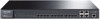
L2 Managed Switch CCCCCCCCCCCConnection 4444 Ethernet Port Connect the Ethernet ports of the Switch to the network devices by RJ45 cable as the following figure shown. RJ45 Port TL-SG5428 RJ45 Cable FFFFFFFFFFFFConnecting the RJ45 Port 4444SFP Port Connect the SFP port to a SFP module. For the switch, if an SFP transceiver (purchased separately) is installed in a slot and has a valid link on the port, the associated RJ45 port will be disabled and cannot be used. Figure 4-2 demonstrates the connection of SFP port to a SFP module. SFP Slot TL-SG5428 SFP Module 13 Connection FFFFFFFFFFFFInserting the SFP Module Optical Fiber Note: A ■■ Combo port refers to two Ethernet interfaces in a device panel (normally one is an SFP slot and the other is an RJ45 port). Inside the device there is only one forwarding interface. Users can choose one to use depending on the actual network requirements, but not two simultaneously. When one port is working, the other is disabled. ■■ For a Combo port, the SFP slot takes priority over its associated RJ45 port. When the SFP slot and its associated RJ45 port are both connected, whatever the priority of connection, the SFP port will always work normally while the RJ45 port will be disabled.
-
 1
1 -
2
-
3
-
4
-
5
-
6
-
7
-
8
-
9
-
10
-
11
-
12
-
 13
13 -
 14
14 -
 15
15 -
 16
16 -
 17
17 -
 18
18 -
 19
19 -
 20
20 -
 21
21 -
 22
22 -
 23
23 -
24
-
25
-
26
-
27
-
28
-
29
-
30
-
31
-
32
 |
 |
