TP-Link TL-WA5110G User Guide - Page 12
Hardware Installation
 |
UPC - 845973051327
View all TP-Link TL-WA5110G manuals
Add to My Manuals
Save this manual to your list of manuals |
Page 12 highlights
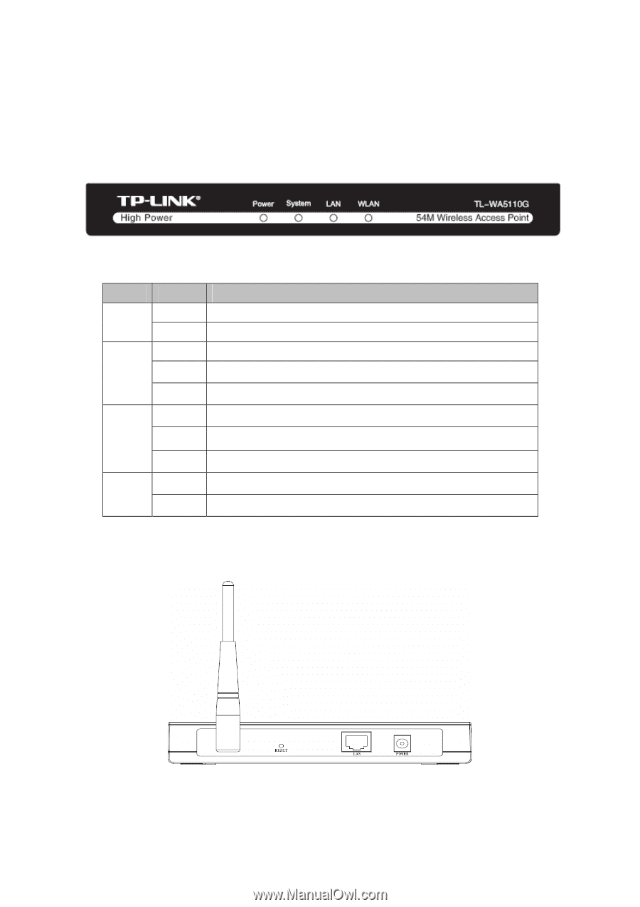
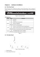
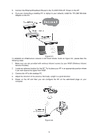
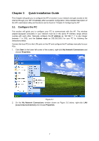
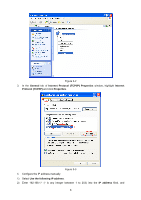
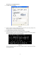
Chapter 2 Hardware Installation 2.1 The Front Panel The front panel of the TL-WA5110G consists of several LED indicators, which is designed to indicate connections. View from left to right. Table 2-1 describes the LEDs on the front panel of the router. LED Explanation: Name Status Off Power On Off Figure 2-1 Front Panel sketch Indication No Power Power on The AP has a hardware error System On The AP is initialising Flashing The AP is working properly Off There is no device linked to the corresponding port LAN On There is a device linked to the corresponding port but no activity Flashing There is an active device linked to the corresponding port WLAN Off The Wireless Radio function is disabled Flashing The Wireless Radio function is enabled Table 2-1 2.2 The Rear Panel Figure 2-2 Rear Panel sketch ¾ Wireless antenna ¾ Factory Default Reset button 4
-
 1
1 -
2
-
3
-
4
-
5
-
6
-
 7
7 -
 8
8 -
 9
9 -
 10
10 -
 11
11 -
 12
12 -
 13
13 -
 14
14 -
 15
15 -
 16
16 -
 17
17 -
18
-
19
-
20
-
21
-
22
-
23
-
24
-
25
-
26
-
27
-
28
-
29
-
30
-
31
-
32
-
33
-
34
-
35
-
36
-
37
-
38
-
39
-
40
-
41
-
42
-
43
-
44
-
45
-
46
-
47
-
48
-
49
-
50
-
51
-
52
-
53
-
54
-
55
-
56
-
57
-
58
-
59
-
60
-
61
-
62
-
63
-
64
-
65
-
66
-
67
-
68
-
69
-
70
-
71
-
72
-
73
-
74
-
75
-
76
-
77
-
78
-
79
-
80
-
81
-
82
-
83
-
84
-
85
-
86
-
87
-
88
-
89
-
90
-
91
-
92
-
93
-
94
-
95
-
96
-
97
-
98
-
99
-
100
-
101
-
102
-
103
-
104
-
105
-
106
-
107
-
108
-
109
 |
 |