TP-Link WBS210 WBS210 V1 Installation Guide - Page 4
Panel Layout - wireless base station
 |
View all TP-Link WBS210 manuals
Add to My Manuals
Save this manual to your list of manuals |
Page 4 highlights
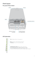
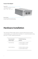
Panel Layout The panel of Base Station Chain1 Chain0 RESET LAN1 LAN0(POE IN) GND Grounding Terminal Shielded Ethernet Port LAN1 Shielded Ethernet Port LAN0(POE IN) LED Explanation On: The Base Station is powered on. On: The port is connected but not active. Flashing: The port is transmitting data. AP/AP Router mode: All four LEDs remain solid. Client/Bridge/Repeater/AP Client Router mode: The more lit LEDs indicate the better wireless signal strength. 2
-
 1
1 -
 2
2 -
 3
3 -
 4
4 -
 5
5 -
 6
6 -
 7
7 -
 8
8 -
 9
9 -
 10
10 -
11
-
12
-
13
-
14
-
15
-
16
-
17
-
18
 |
 |

The panel of Base Station
Panel Layout
RESET
Shielded
Ethernet
Port LAN1
Shielded
Ethernet
Port LAN0(POE IN)
Grounding Terminal
2
AP/AP Router mode:
All four LEDs remain solid.
Client/Bridge/Repeater/AP Client Router mode:
The more lit LEDs indicate the better wireless signal strength.
On:
The port is connected but not active.
Flashing:
The port is transmitting data.
On:
The Base Station is powered on.
LED Explanation
LAN1
LAN0(POE IN)
GND
Chain1
Chain0