Toshiba 50H81 Service Manual - Page 10
Self Diagnostic Function, Selecting The Adjusting Items, Adjusting The Data, Exit From Service Mode - manual
 |
View all Toshiba 50H81 manuals
Add to My Manuals
Save this manual to your list of manuals |
Page 10 highlights
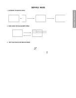
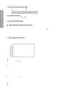
GENERAL ADJUSTMENTS SPECIFIC INFORMATIONS 4. SELECTING THE ADJUSTING ITEMS 1) Every pressing of CHANNEL s button in the service mode changes the adjustment items in the order of table-2. (t button for reverse order) Refer to table-2 for preset data of adjustment mode. (See SETTING & ADJUSTING DATA on page 17) 5. ADJUSTING THE DATA 1) Pressing of VOLUME s or t button will change the value of data in the range from 00H to FFH. The variable range depends on the adjusting item. 6. EXIT FROM SERVICE MODE 1) Pressing POWER button to turn off the TV once. I INITIALIZATION OF MEMORY DATA OF QA02 After replacing QA02, the following initialization is required. 1. Enter the service mode, then select any register item. 2. Press and hold the RECALL button on the Remote, then press the CHANNEL s button on the TV. The initialization of QA02 has been complated. 3. Check the picture carefully. If necessary, adjust any adjustment item above. Perform "Programming Channel Memory" on the owner's manual. CAUTION: Never attempt to initialize the data unless QA02 has been replaced. 7. SELF DIAGNOSTIC FUNCTION 1) Press "9" button on Remote Control during display of adjustment menu in the service mode. The diagnosis will begin to check if interface among IC's are executed properly. 2) During diagnosis, the following displays are shown. SELF CHECK ᕃ NO. 23 * * * * * * ᕄ POWER : 000 ᕅ BUS LINE : OK ᕆ BUS CONT : OK ᕇ BLOCK : MAIN SUB ᕈ SET ID : 01 ᕉ EEP VER : 02 ᕊ OPT1 : 05 OPT2 : 70 ᕃ Part number of microprocessor (QA01) ᕄ Operation number of protection circuit (current limiter) . . . . "000" is normal. ᕅ BUS line check "OK Normal "SCL-GND" or "NG SCL-GND short circuit "SDA-GND" or "NG SDA-GND short circuit "SCL-SDA" or "NG SCL-SDA short circuit ᕆ BUS line ACK (acknowledge) check "OK Normal Display of Location Number . . . . NG (Display example) "QA02 NG", "H001 NG", "Q501 NG" etc. Note: The indication of failure place is only one place though failure places are plural. When repair of a failure place finishes, the next failure place is indicated. (The order of priority of indication is left side.) ᕇ Sync. signal check Green display ..... Normal Red display ........ NG ᕈ ID code for TV Set ᕉ Version of "EEP" ᕊ Data for "OPT" MAIN ........ Main sync SUB .......... Sub sync (when turn on the PIP) - 10 -
-
 1
1 -
2
-
3
-
4
-
 5
5 -
 6
6 -
 7
7 -
 8
8 -
 9
9 -
 10
10 -
 11
11 -
 12
12 -
 13
13 -
 14
14 -
 15
15 -
16
-
17
-
18
-
19
-
20
-
21
-
22
-
23
-
24
-
25
-
26
-
27
-
28
-
29
-
30
-
31
-
32
-
33
-
34
-
35
-
36
-
37
-
38
-
39
-
40
-
41
-
42
-
43
-
44
-
45
-
46
-
47
-
48
-
49
-
50
-
51
-
52
-
53
-
54
-
55
-
56
-
57
-
58
-
59
-
60
-
61
-
62
-
63
-
64
-
65
-
66
 |
 |
